
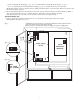
Installation Instructions

Altronix is not responsible for any typographical errors.
Altronix Corp.
140 58th Street, Brooklyn, New York 11220 USA, 718-567-8181, fax: 718-567-9056
web site: www.altronix.com, e-mail: info@altronix.com, Made in U
.S.A.
IISMP7CTX - Rev. 120104
L01D
00
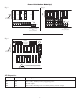
0
.81"
0
1.1875"
1.1875"
3.25"
3.25"
0 1.1875" 3.25".75" 1.5" 6.25" 11"
1.4"
6.5"
5.5"
1.4"
11.66"
12.1"
13"
12.5"
11.75"
TOP ONLY
Enclosure Dimensions:
13”H x 13.5”W x 3.25”D
- 4 -
MEMBER
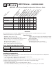
Terminal Identification:
Terminal Function/Description
Legend
L, G, N Connect 115VAC to these terminals:
L to Hot, N to Neutral, G to ground (if used).
+ DC - 12VDC / 24VDC @ 6 amp continuous non-power limited output.
*AC FAIL Used to notify loss of AC power, e.g. connect to audible device or alarm
N.O., C, N.C. panel. Relay normally energized when AC power is present.
Contact rating 1 amp @ 120VAC / 28VDC
*Low Battery Used to indicate low battery condition, e.g. connect to alarm panel.
N.O., C, N.C. Relay normally energized when DC power is present.
Contact rating 1 amp @ 120VAC / 28VDC
Low battery threshold:
12VDC output threshold set @ approximately 10.5VDC,
24VDC output threshold set @ approximately 21VDC.
- BAT + Stand-by battery connections. Maximum charge rate .7 amp.
* Note: Supervised models only
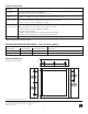
PD4/PD4CB/PD8/PD8CB/PD16W/PD16WCB - Power Distribution Module
Terminal Legend Function/
PD4/PD4CB PD8/PD8CB PD16W/PD16WCB Description
1P to 4P 1P to 8P 1P to16P Positive DC power outputs.
1N to 4N 1N to 8N 1N to 16N Negative DC power outputs.