
Installation Manual

SMP5PM - 1 -
SMP5PM - Supervised Power Supply/Charger
Overview:
SMP5PM is a supervised power supply/charger that converts a low voltage AC input into a 12VDC or 24VDC selectable
output with 4 amp of continuous supply current (see specifications).
Specifications:
Voltage Output/Transformer Selection Table:
Output VDC Switch Position Max. Load DC Transformer Requirements
12VDC SW1 Closed 4 amp 24VAC or 28VAC / 100VA (T2428100)
24VDC SW1 Open 4 amp 24VAC or 28VAC / 175VA (T2428175)
Note: Transformers with higher VA ratings may be used for all output voltages above as long as you
do not exceed 28VAC or 45VDC.
Installation Instructions:
The SMP5PM should be installed in accordance with the National Electrical Code and all applicable Local Regulations.
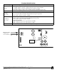
1. Mount SMP5PM board in the desired location/enclosure.
2. Set SMP5PM to the desired DC output voltage via SW1 (Voltage Output/Transformer Selection Table).
3. Connect proper transformer to the terminals marked [AC] (Voltage Output/Transformer Selection Table).
Use 18 AWG or larger for all power connections (Battery, DC output).
Use 22 AWG to 18 AWG for power-limited circuits (AC Fail/Low Battery reporting).
Keep power-limited wiring separate from non power-limited wiring (115VAC / 60Hz Input, Battery Wires).
Minimum 0.25” spacing must be provided.
CAUTION: Do not touch exposed metal parts. Shut branch circuit power before installing or servicing equipment.
There are no user serviceable parts inside. Refer installation and servicing to qualified service personnel.
4. Measure output voltage before connecting devices. This helps avoiding potential damage.
5. Connect devices to be powered to the terminals marked [ + DC -- ].
6. When the use of stand-by batteries is desired, they must be lead acid or gel type.
Connect battery to the terminals marked [ + BAT -- ] on the board (battery leads included).
Use two (2) 12VDC batteries connected in series for 24VDC operation.
Note: When batteries are not used, a loss of AC will result in the loss of output voltage.
7. Connect appropriate signaling notification devices to AC Fail & Low battery supervisory relay outputs marked [NC, C, NO].
LED Diagnostics:
Red (DC) Green (AC) Power Supply Status
ON ON Normal operating condition
ON OFF Loss of AC. Stand-by battery supplying power.
OFF ON No DC output.
Off Off Loss of AC. Discharged or no standby by battery. No DC output.
Input:
• 24VAC or 28VAC
(See Voltage Output/Transformer Selection Table).
Output:
• 12VDC or 24VDC selectable output.
• 4 amp supply current.
• Filtered and electronically regulated outputs.
• Short circuit and thermal overload protection.
Battery Backup:
• Built-in charger for sealed lead acid or gel type batteries.
• Maximum charge current 0.3 amp.
Battery Backup (cont’d):
• Zero voltage drop when switching over
to battery backup.
Supervision:
• AC fail supervision (form “C” contacts).
• Low battery supervision (form “C” contacts).
Indicators:
• AC input and DC output LED indicators.
Board Dimensions (W x L x H approximate):
7” x 4.05” x 1.35” (177.8mm x 102.87mm x 34.29mm)