
Installation Guide


- 4 - SMP10C12Xseries
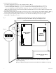
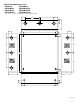
INPUT
LED
PD4
POWER DISTRIBUTING UNIT
1P, 2P, 3P, 4P = FUSED OUTPUTS
1N, 2N, 3N, 4N = COMMON OUTPUTS
F1
F1
F2 F3 F4
COMMON POWER OUTPUTS
1P
1N
2P
2N
3P
3N
4P
4N
DC Output to devices
From Power Supply
Board
(Factory Installed)
Used
on PTC
Models
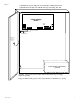
PD8
N
COMMON POWER OUTPUTS
P
FUSED POWER OUTPUTS
1 2 3 4 5 6 7 8
1
D1
INPUT
R1
LED
DC Output to devices
From Power Supply
Board
(Factory Installed)
Used
on PTC
Models
Fig. 3 Fig. 4
Power Distribution Module(s):
LED Diagnostics:
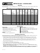
Power Supply Board
Red (DC) Green (AC) Power Supply Status
ON ON Normal operating condition.
ON OFF Loss of AC. Stand-by battery supplying power.
OFF ON No DC output.
OFF OFF Loss of AC. Discharged or no stand-by battery. No DC output.
PD4/PD4CB/PD8/PD8CB/PD16W/PD16WCB - Power Distribution Module
Green Power Distribution Module Status.
ON Normal operating condition.
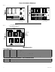
3.5A 250V
For continuous protection against
risk of fire replace fuses with
same type and rating.
common
outputs
protected
outputs
P
N
NPS
XFMR Input
12345678
9 10 11 12 13 14 15 16
NP
DC Output to devices
1P-16P Power Outputs,
1N-16N Common Outputs
)
)
From Power
Supply
Board
(Factory
Installed)
1
Used
on PTC
Models
Fig. 5