™ DC CCTV Power Supplies Installation Guide Models Include: Sav4D - 12VDC @ 5 amp - Four (4) Class 2 Rated PTC Protected Power-Limited Outputs. Sav9D - 12VDC @ 5 amp - Nine (9) Class 2 Rated PTC Protected Power-Limited Outputs. Sav18D - 12VDC @ 5 amp - Eighteen (18) Class 2 Rated PTC Protected Power-Limited Outputs. Sav182D - 12VDC @ 11 amp - Eighteen (18) Class 2 Rated PTC Protected Power-Limited Outputs.
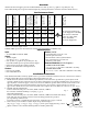
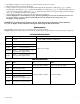
Overview: Altronix Sav Power Supplies provide 12VDC distributed via four (4), nine (9), eighteen (18), thirty-six (36) Class 2 Rated PTC protected power-limited outputs for powering Surveillance Cameras and other 12VDC devices. Sav4D 5 amp 12VDC 4 2.5 amp* 1.5 amp 0.75 amp Sav9D 5 amp 12VDC 9 2.5 amp* 1.5 amp 0.75 amp Sav18D 5 amp 12VDC 18 2.5 amp* 1.5 amp 0.75 amp Sav182D 11 amp 12VDC 18 2.5 amp* 3 amp 1.5 amp Sav36D 12VDC 36 2.5 amp* 3 amp 1.
turn trimpot clockwise to increase voltage or counter clockwise to decrease voltage. Note: Voltage will be the same for all outputs. 4. Connect cameras to be powered to the terminals marked [OUT1 through OUT4 (Sav4D)] (Fig. 2, pg. 4), [OUT1 through OUT9 (Sav9D)] (Fig. 3, pg. 5), [OUT1 through OUT18 (Sav18D)] (Fig. 4, pg. 6), [OUT1 through OUT9 on each power supply board (Sav182D)] (Fig. 5, pg. 7), [OUT1 through OUT18 on each power supply board (Sav36D)] (Fig. 6, pg.
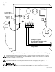
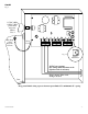
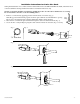
Sav4D Fig. 2 115VAC, 60Hz/ 230VAC, 50Hz power mains non powerlimited Class 1 Wire Strap (from Enclosure to Door) Green Lead Fig. 2a Voltage Adjustment 12VDC power outputs (For wiring utilize knockouts on the right hand side of enclosure) Class 2 not wet, Class 3 wet, wiring to be used. Door Keep power-limited wiring separate from non power-limited. Use minimum 0.25" spacing.
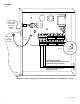
Sav9D Fig. 3 115VAC, 60Hz/ 230VAC, 50Hz power mains non powerlimited Class 1 Wire Strap (from Enclosure to Door) Green Lead Fig. 3a Voltage Adjustment 12VDC power outputs (For wiring utilize knockouts on the right hand side of enclosure) Class 2 not wet, Class 3 wet, wiring to be used. Door Keep power-limited wiring separate from non power-limited. Use minimum 0.25" spacing.
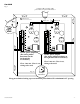
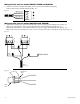
Sav18D Fig. 4 115VAC, 60Hz/ 230VAC, 50Hz power mains non powerlimited Class 1 Wire Strap (from Enclosure to Door) Green Lead Fig. 4a Voltage Adjustment 12VDC power outputs (For wiring utilize knockouts on the right hand side of enclosure) Class 2 not wet, Class 3 wet, wiring to be used. Door Keep power-limited wiring separate from non power-limited. Use minimum 0.25" spacing.
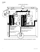
Sav182D Fig. 5 115VAC, 60Hz / 230VAC, 50Hz power mains non power-limited Class 1 Green Lead Black Lead 12VDC power outputs (For wiring utilize knockouts on the left hand side of enclosure) 12VDC power outputs (For wiring utilize knockouts on the right hand side of enclosure) Class 2 not wet, Class 3 wet, wiring to be used. Fig. 5a White Lead Class 2 not wet, Class 3 wet, wiring to be used. Voltage Adjustment Keep power-limited wiring separate from non power-limited. Use minimum 0.25" spacing.
Sav36D Fig. 6 115VAC, 60Hz / 230VAC, 50Hz power mains non power-limited Class 1 Green Lead Black Lead 12VDC power outputs (For wiring utilize knockouts on the left hand side of enclosure) White Lead 12VDC power outputs (For wiring utilize knockouts on the right hand side of enclosure) Class 2 not wet, Class 3 wet, wiring to be used. Class 2 not wet, Class 3 wet, wiring to be used. Fig. 6a Voltage Adjustment Keep power-limited wiring separate from non power-limited. Use minimum 0.25" spacing.
Installation Instructions for 3-wire Line Cord: Wiring methods shall be in accordance with the National Electrical Code/NFPA 70/NFPA 72/ANSI, and with all local codes and authorities having jurisdiction. Product is intended for indoor use only. The line cord option should be used when the equipment needs to be removed for maintenance or servicing. Do not attach the 3-wire line cord to the building surface. 1. Remove 7/8” knockout by applying pressure from the inside of enclosure (Fig. 7).
Wiring AC line cord for models SAV4D, SAV9D and SAV18D: 1. Connect black lead to terminal marked [L]. Connect green lead to terminal marked [G]. Connect white lead to terminal marked [N] (Fig. 11). Fig. 11 White Lead Green Lead Black Lead Wiring AC line cord for models SAV182D and SAV36D: 1. Splice black lead from line cord to black leads from each power supply board utilizing wire nut (Fig. 12). Splice green lead from line cord to green flying lead in the enclosure utilizing wire nut (Fig. 12).
Enclosure Dimensions for Sav4D, Sav9D and Sav18D: 8.5” x 7.5” x 3.5” (215.9mm x 190.5mm x 88.9mm) 7.25” (184.15mm) 3.625” (184.15mm) 1.25” (31.75mm) 3.5” (88.9mm) 1.25” (31.75mm) 2” (50.8mm) 0.6” (15.24mm) 0.6” (15.24mm) 6.05” (153.67mm) 1.125” (28.575mm) 1.125” (28.575mm) 2” (50.8mm) 8.125” (206.375mm) 1” (25.4mm) 1” (25.4mm) 6.05” (153.67mm) 0.6” (15.24mm) 0.6” (15.24mm) 1.25” (31.75mm) 3.5” (88.9mm) 1” (25.4mm) 1” (25.4mm) Sav4/9/18/182/36D 5.25” (133.35mm) 1” (25.
Enclosure Dimensions for Sav182D and Sav36D: 13.5” x 13” x 3.25” (342.9mm x 330.2mm x 82.55mm) 1.40” (36mm) 4.85” (123mm) 4.85” (123mm) 1.40” (36mm) 1.20” (31mm) 3.25” (83mm) 1.20” (31mm) 0.75” (19mm) 12.5” (318mm) 11.0” (279mm) 1.20” (31mm) 0.75” (19mm) 0.9375” (24mm) 1.40” (36mm) 1.40” (36mm) 5.10” (130mm) 5.10” (130mm) 13.0” (330mm) 5.10” (130mm) 6.5625” (167mm) 0.9375” (24mm) 3.25” (83mm) 3.25” (83mm) 3.25” (83mm) 1.0” (25mm) 1.0” (25mm) 1.0” (25mm) 10.5” (267mm) 1.