
Installation Instructions Owner manual


ReServ - 2 -
WARNING: To reduce the risk of fire or electric shock, do not expose the unit to rain or moisture.
This installation should be made by qualified service personnel and should conform to all local codes and
in accordance with the National Electrical Code.
LED Diagnostics:
Power Supply Board
Red (DC) Green (AC1) Power Supply Status
ON ON Normal operating condition.
ON OFF Loss of AC, Stand-by battery supplying power.
OFF ON No DC output.
OFF OFF Loss of AC. Discharged or no stand-by battery. No DC output.
ReServ Board
LED LED State Unit Status
Output LEDs
ON ------ Normal operating condition.
------ OFF Loss of 24VACand/or 12VDC output power.
Low Battery
ON ------ Stand-by batteries are low.
------ OFF Normal operating condition.
Shutdown
ON ------ Loss of 24VACand/or 12VDC output power. Discharged stand-by battery.
------ OFF Normal operating condition.
Terminal Identification:
Power Supply Board
Terminal Legend Function/Description
L, G, N Connect 115VAC 60Hz to these terminals: L to hot, N to neutral, G to ground.
-- DC + 24VDC non-power limited output.
AC FAIL
NO, C, NC
Form “C” dry contacts used to instantaneously signal the loss AC to local annunciation devices,
with AC present terminals marked NO and C are open, NC and C are closed. When loss of AC
occurs terminals marked NO and C are closed, NC and C are open.
BAT FAIL
NO, C, NC
Form “C” dry contacts used to signal low battery voltage or loss of battery voltage. Under normal
conditions terminals marked NO and C are open, NC and C are closed. During a trouble condition
terminals marked NO and C are closed, and NC and C are open.
-- BAT + Stand-by battery connections. Maximum charge current 0.7 amp.
ReServ Board
Terminal Legend Function/Description
Input --- 24VDC + 24VDC input from power supply board.
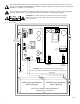
N, P 1-2 12VDC outputs. N = Negative, P = Positive (Fig. 1, pg. 3).
N, P 15-16 24VAC outputs.