
Installation Instructions

ReServ4WP - 2 -
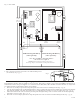
To reset the PTC:
1. Temporarily remove wiring from output with tripped PTC (Fig. 2, pg. 3).
2. Eliminate the trouble condition (short circuit or overload).
3. Allow 1 minute for PTC to cool off (reset).
4. Re-attach wiring to the output (Fig. 2, pg. 3).
5. Power LEDs will illuminate indicating power has been restored to outputs (Fig. 2, pg. 3).
WARNING: To reduce the risk of fire or electric shock, do not expose the unit to rain or moisture. This installation
should be made by qualified service personnel and should conform to the National Electrical Code and all local codes.
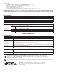
LED Diagnostics:
Power Supply Board
Red (DC) Green (AC1) Power Supply Status
ON ON Normal operating condition.
ON OFF Loss of AC. Stand-by battery supplying power.
OFF ON No DC output.
OFF OFF Loss of AC. Discharged or no stand-by battery. No DC output.
ReServ Board
LED LED State Unit Status
Output LEDs
ON ------ Normal operating condition.
------ OFF Loss of 24VAC and/or 12VDC output power.
Low Battery
ON ------ Stand-by batteries are low.
------ OFF Normal operating condition.
Shutdown
ON ------ Loss of 24VAC and/or 12VDC output power. Discharged stand-by battery.
------ OFF Normal operating condition.
Terminal Identification:
Power Supply Board
Terminal Legend Function/Description
L, G, N Connect 115VAC 60Hz to these terminals: L to hot, N to neutral.
-- DC + 24VDC output.
AC FAIL
NO, C, NC
Form “C” dry contacts used to instantaneously signal the loss AC to local annunciation devices, with AC
present terminals marked NO and C are open, NC and C are closed. When loss of AC
occurs, terminals marked NO and C are closed, NC and C are open.
BAT FAIL
NO, C, NC
Form “C” dry contacts used to signal low battery voltage or loss of battery voltage. Under normal conditions
terminals marked NO and C are open, NC and C are closed. During a trouble condition terminals marked
NO and C are closed, and NC and C are open.
-- BAT + Stand-by battery connections. Maximum charge current 0.7A.
ReServ Board
Terminal Legend Function/Description
Input --- 24VDC + 24VDC input from power supply board.
N, P 1-2 12VDC outputs. N = Negative, P = Positive (Fig. 1, pg. 3).
N, P 15-16 24VAC outputs.
The lightning flash with arrow head symbol within an equilateral triangle is intended to alert the user to the
presence of an insulated DANGEROUS VOLTAGE within the product’s enclosure that may be of sufficient
magnitude to constitute an electric shock.
The exclamation point within an equilateral triangle is intended to alert the user to the presence of important operating and
maintenance (servicing) instructions in the literature accompanying the appliance.
CAUTION: To reduce the risk of electric shock do not open enclosure.
There are no user serviceable parts inside. Refer servicing to qualified
service personnel.