
Installation Instructions

ReServWP - 3 -
5. Connect AC power mains to the terminals marked [L] and [N], (Figs. 2-3, pg. 5-6).
Use 18 AWG or larger for all power connections (Battery, output) (Figs. 2-3, pg. 5-6).
Use 18 AWG to 22 AWG for power-limited circuits (AC Fail/Low Battery reporting) (Figs. 2-3, pg. 5-6).
Note: A readily accessible disconnect device shall be incorporated in the building installation wiring.
Keep power-limited wiring separate from non power-limited wiring (115VAC 60Hz Input, Battery Wires).
Minimum 0.25” spacing must be provided.
CAUTION: Do not touch exposed metal parts. Shut branch circuit power before installing or servicing equipment.
There are no user serviceable parts inside. Refer installation and servicing to qualified service personnel.
6. The LEDs on the power supply board will illuminate when AC power is present.
7. Measure output voltage before connecting cameras/devices to outputs. This helps avoiding potential damage.
8. ReServ3WP only - Adjust voltage for every two (2) outputs using the corresponding trimpot(s) on the board prior
to connecting devices.
9. Connecting cameras/devices:
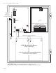
ReServ1WP - Connect 12VDC cameras/devices to the terminals marked [P 1-4, N 1-4] (Fig. 2, pg. 5).
Connect 24VAC cameras/devices to the terminals marked [5-16] (Fig. 2, pg. 5).
ReServ2WP - Connect 24VAC cameras/devices to the terminals marked [1-16] (Fig. 2, pg. 5).
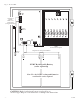
ReServ3WP - Connect 12VDC cameras/devices to the terminals marked [P 1-16, N 1-16] (Fig. 3, pg. 6).
10. Connect batteries to the terminals marked [-- BAT + ] (Figs. 2-3, pg. 5-6). Use two (2) 12VDC batteries connected in
series for 24VDC operation (battery leads included).
Use batteries - Casil CA1270 (12V/7AH), Genesis NP7-12 (12V/7AH) or NP7-12 (12V/12AH), Ultratech UT1270
(12V/7AH) or Ultratech UT12120 (12V/12AH).
11. Connect appropriate signaling notification devices to AC FAIL and BAT FAIL (Figs. 2-3, pg. 5-6)
supervisory relay outputs.
12. The power LEDs on the unit for Outputs 1-16 will illuminate when AC power is present (Figs. 2-3, pg. 5-6).
Note: If any of the power LEDs are not illuminated the cause may be due to the following:
a. AC mains and battery fail.
b. One (1) or more power output PTCs are tripped due to a short circuit or overload condition.
c. Unit damaged/defective.
To reset the PTC:
1. Disconnect corresponding camera/device connected to terminals marked [1-16] (Figs. 2-3, pg. 5-6).
2. Eliminate the trouble condition (short circuit or overload).
3. Allow 1 minute for PTC to cool off (reset).
4. Connect corresponding cameras/devices to terminals marked [1-16] (Figs. 2-3, pg. 5-6).
5. Power LEDs will illuminate indicating power has been restored to outputs (Figs. 2-3, pg. 5-6).
WARNING: This installation should be made by qualified service personnel and should conform to all
local codes and in accordance with the National Electrical Code.
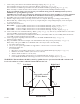
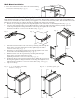
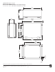
Right PanelLeft Panel
Suggested Locations
for Wire Entries
Bottom Panel
Fig. 1