
Installation Instructions User Manual

- 2 - R248 series
Overview:
These Altronix Rack Mount CCTV Power Supplies provide 24VAC or 28VAC distributed via eight (8) fuse or PTC
protected outputs for powering CCTV Cameras, heaters and other video accessories.
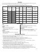
Eight (8) Output Rack Mount Configuration Reference Chart:
Altronix
Model Number
Output
Voltage
(VAC)
Total Output
Current
(Power)
Number of
Outputs
PTC
Protected
Outputs
Fuse
Protected
Outputs
Individual Output
Current
(max per output -
not to exceed total
output current)
115VAC
50/60Hz Input
Current
R248100
24VAC 4 amp
8 --- Yes 3.5 amp 2.9 amp
28VAC 3.5 amp
R28100CB
24VAC 4 amp
8 Yes --- 2.5 amp 2.9 amp
28VAC 3.5 amp
R248300
24VAC 14 amp
8 --- Yes 3.5 amp 3 amp
28VAC 12.5 amp
R28300CB
24VAC 14 amp
8 Yes --- 2.5 amp 3 amp
28VAC 12.5 amp
R248600
24VAC 28 amp
8 --- Yes 3.5 amp 6 amp
28VAC 25 amp
R248600CB
24VAC 28 amp
8 Yes --- 2.5 amp 6 amp
28VAC 25 amp
Specifications:
Installation Instructions:
1. Mount unit in the desired rack location (Space unit at least 3” from any video monitors). Do not obstruct side air vents.
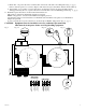
2. Set power disconnect circuit breaker to OFF position (Fig. 1c, pg. 3).
3 All units are factory set for 24VAC operation.
For 28VAC operation, adjust unit prior to mounting and applying power as follows:
Change the wire position so that the black wire [28V] is connected to the terminal marked [P] and
the yellow wire [24V] is connected to the terminal marked [S] (Fig. 1, pg. 3).
4. Plug power cord into a grounded 115VAC 50/60 Hz receptacle (Fig. 1b, pg. 3), ground should be connected
as indicated in (Fig. 1d, pg. 3).
5. Set power disconnect circuit breaker to RESET (ON) position (Fig. 1c, pg. 3).
6. Measure output voltage before connecting devices. This helps avoiding potential damage.
All terminals with common suffix (P) “1P, 2P...” are the same polarity.
7. Set power disconnect circuit breaker to OFF position (Fig. 1c, pg. 3).
8. Connect devices to the removable terminal blocks marked [1P & 1N through 8P & 8N] (Fig. 1a, pg. 3).
When wiring is completed on terminal blocks, they can be locked down by tightening screw flanges.
9. Upon completion of wiring, set power disconnect circuit breaker to RESET (ON) position (Fig. 1c, pg. 3).
10. Green power LEDs on faceplate will illuminate when power is present. When an output is in a trouble condition
(blown fuse or tripped PTC), the corresponding LED will not be illuminated (Fig. 1, pg. 3).
Input:
• 115VAC,50/60Hz.
Output:
• Eight (8) fuse or PTC protected outputs.
• 24VACor28VACsupplycurrent.
• Outputs are rated @ 3.5 amp (fuse) or 2.5 amp (PTC).
• Surgesuppression.
Features:
• Eight(8)powerLEDs.
• Illuminatedmasterpowerdisconnectcircuitbreaker
with manual reset.
Features (cont’d):
• Removableterminalblockswithlockingscrewflange.
• Spare fuses provided.
• Unitmaintainscamerasynchronization.
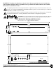
Mechanical:
• 2UrackmountchassisforuseinstandardEIA19”rack.
• EnclosureDimensions(HxWxDapprox.):
3.26” x 19.125” x 8.5” (83mm x 486mm x 216mm).