
Installation Instructions User Manual

- 2 - R1224DC16CB
Overview:
These Altronix Rack Mount Power Supplies provide 12VDC or 24VDC distributed via sixteen (16) PTC protected
Class 2 Rated outputs for power limited installation.
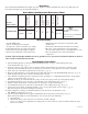
Rack Mount Configuration Reference Chart:
Altronix
Model Number
Output Voltage
Total Output
Current (Power)
Number of
Ouputs
Class 2 Rated
Power Limited
Outputs
PTC Protected
Outputs
Output Current
(max per output)
115VAC 60Hz
Input Current
Agency Listing
R1224DC16CB
12VDC 18 amp
16
3 3
2
amp
3.74 amp
Specialty Power Supply
UL1012
CUL Listed - CSA Standard
C22.2 No.107.1
24VDC 18 amp
6.26 amp
Specifications:
Caution: This installation should be made by qualified service personnel and should conform to all local
codes and the National Electrical Code.
Installation Instructions:
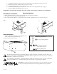
1. Attach mounting brackets to unit for rack mount installation (Fig. 1a, pg. 3). Affix rubber pads to unit
for shelf installation (Fig. 2, pg. 3).
2. Secure the unit in a rack or place unit on a shelf as desired (unit should be spaced at least 3” from any video
monitors). When installing the unit in a rack allow for one half of a U spacing above the unit for ventilation.
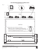
3. Insert and secure removable terminal blocks to unit (Fig. 3c, pg. 4).
4. Plug the grounded AC line cord (included) into the IEC 320 connector of the R1224DC16CB unit (Fig. 3a, pg. 4).
Insert the plug end of the line cord into a grounded AC receptacle.
5. Select 12VDC or 24VDC power for each group of four (4) outputs 1a - 1d through 4a-4d with the corresponding
voltage selector switches (Fig. 3b, pg. 4).
Note: Each voltage selector switch sets the voltage for the entie group of four (4) corresponding outputs.
6. Set illuminated master power disconnect circuit breaker to the (ON) position (Fig. 3d, pg. 4).
7. Measure output voltage before connecting devices. This helps avoid potential damage.
8. Set illuminated master power disconnect circuit breaker to the (OFF) position (Fig. 3d, pg. 4).
9. Connect the power output of terminals marked [+ 1A -- ] to the power inputs of device (Fig. 3c, pg. 4).
Repeat this step for the other remaining power outputs.
10. Upon completion of wiring, set illuminated master power disconnect circuit breaker to the
ON (RESET) position (Fig. 3d, pg. 4).
11. All four (4) power LEDs on the faceplate will illuminate when AC power is present (Fig. 1a, pg. 4).
Note: If the power LEDs are not illuminated the cause may be due to the following:
a. AC mains fail.
b. Illuminated master power disconnect circuit breaker is OFF or tripped.
If one (1) or more power output PTCs are tripped due to a short circuit or overload condition follow the steps
below to reset PTC:
•115VAC60Hzinput.
•Sixteen(16)PTCprotectedoutputs.
•18amptotal(current12ampmax.peroutput)
•PowerLEDindicatorspergroupof4outputs.
•Filteredandelectronicallyregulatedoutputs.
•Shortcircuitandthermaloverloadprotection.
•Illuminatedpowerdisconnectcircuitbreakerwith
manual reset.
•Removableterminalblocksw/lockingscrewflange.
•IEC320-3-wiregroundedlinecord(detachable).
•3UrackmountchassisforuseinstandardEIA19”rack.
•Easeofinstallationsavestimeandeliminates
costly labor.