
Installation Guide

- 2 - OLS120D2X Installation Guide
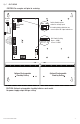
8. Connect 12VDC or 24VDC (depending on DIP switch setting) device to be powered to the terminals
marked [– DC1 +]. Connect 12VDC device to be powered to the terminals marked [– DC2 +]
(Fig. 1, pg. 3).
9. When use of stand-by batteries is desired, they must be lead acid or gel type.
Connect battery/batteries to the terminals marked [– BAT + ]
(Fig. 1, pg. 2).
12VDC operation only: Use one (1) 12VDC battery for 12VDC backup.
24VDC and 12VDC simultaneous operation: Use two (2) 12VDC batteries connected in series for
24VDC backup.
10. When batteries are not used, a loss of AC will result in the loss of output voltage.
11. Connect appropriate signaling notification devices to AC Fail & Low battery supervisory
relay outputs marked [NC, C, NO].
12. Slide [Power ON/OFF] switch to the ON position
(Fig. 1, pg. 3).
Maintenance:
Unit should be tested at least once a year for the proper operation as follows:
Output Voltage Test: Under normal load conditions, the DC output voltage should be checked for
proper voltage level.
Battery Test: Under normal load conditions check that the battery is fully charged, check specified
voltage (12VDC @ 13.7 or 24VDC @ 27.4) both at the battery terminal and at the board
terminals marked [– BAT +] to ensure that there is no break in the battery connection
wires. Note: Maximum charging current under discharges is 0.7A.
Note: Expected battery life is 5 years; however, it is recommended changing batteries
in 4 years or less if needed.
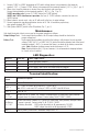
LED Diagnostics:
Red (DC1) Green (AC) Power Supply Status
ON ON Normal operating condition.
ON OFF Loss of AC. Stand-by battery is supplying power.
OFF ON No DC output. Short circuit or thermal overload condition.
OFF OFF Loss of AC. Discharged or no stand-by battery. No DC output.
Terminal Identification:
Terminal
Legend
Function/Description
L, G, N Connect 115VAC/230VAC to these terminals: L to Hot, N to Neutral.
– DC1 +
DC1 - 12VDC or 24VDC @ 3A and DC2 - 12VDC @ 1A
Note: If DC2 is not used, DC1 rating is 12VDC or 24VDC rated @ 4A max.
– DC2 + 12VDC @ 1A.
AC FAIL
NC, C, NO
Indicates loss of AC power, e.g. connect to audible device or alarm panel. Relay normally
energized when AC power is present. Contact rating 1A @ 115VAC / 28VDC
Low Battery
NC, C, NO
Indicates low battery condition, e.g. connect to alarm panel. Relay normally energized when
DC power is present. Contact rating 1A @ 115VAC / 28VDC.
Low battery threshold: 2VDC output threshold set @ approximately 10.5VDC,
24VDC output threshold set @ approximately 21VDC.
– BAT + Stand-by battery connections. Maximum charge rate 0.7A.