
Installation Instructions

Maximal3F/Maximal5F/Maximal7F Access Power Controllers (Fused) - 3 -
eFlow Power Supply/Charger:
• Input: 120VAC, 60Hz.
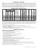
• For output voltage and supply current refer to MaximalF series Configuration Chart, pg. 2.
• Auxiliary power-limited output rated @ 1 amp (unswitched).
• Overvoltage Protection.
• Built-in charger for sealed lead acid or gel type batteries.
• Maximum charge current 1.54 amp.
• Automatic switch over to stand-by battery when AC fails. Transfer to stand-by battery power is instantaneous with no interruption.
• Supervised Fire Alarm disconnect (latching or non-latching) 10K EOL resistor. Operates on a normally open (NO) or
normally closed (NC) trigger.
• AC fail supervision (form “C” contacts).
• Battery fail & presence supervision (form “C” contacts).
• Low power shutdown. Shuts down DC output terminals if battery voltage drops below 71-73% for 12V units and 70-75%
for 24V units (depending on the power supply). Prevents deep battery discharge.
• For fuse ratings refer to MaximalF Series Configuration Chart, pg. 2.
• Green AC Power LED indicates 120VAC present.
• AC input and DC output LED indicators.
• Short circuit and overload protection.
• Enclosure accommodates up to four (4) 12VDC/12AH batteries.
Enclosure dimensions (H x W x D): 26” x 19” x 6.25” (660.4mm x 482.6mm x 158.75mm).
MaximalF Installation Instructions:
Wiring methods shall be in accordance with the National Electrical Code/NFPA 70/ANSI, The Canadian Electric Code, Part I,
Part II, and with all local codes and authorities having jurisdiction. Product is intended for indoor use only.
Power Supply Board LED Diagnostics (pg. 5)
Access Power Controller LED Diagnostics (pg. 5)
Power Supply Board Terminal Identification (pg. 5)
Access Power Controller Terminal Identification (pg. 5)
Power Supply Board Stand-by Battery Specifications (pg. 6)
Power Supply Board Output Voltage Settings (pg. 6)
Access Power Controller Typical Application Diagram (pg. 6)
FACP Hook-up Diagrams (pg. 9)
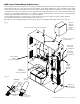
1. Mount unit in desired location. Mark and predrill holes in the wall to line up with the top three keyholes in the
enclosure. Install three upper fasteners and screws in the wall with the screw heads protruding. Place the enclosure’s
upper keyholes over the three upper screws, level and secure. Mark the position of the lower three holes.
Remove the enclosure. Drill the lower holes and install the three fasteners. Place the enclosure’s upper keyholes
over the three upper screws. Install the three lower screws and make sure to tighten all screws
(Enclosure Dimensions, pg. 12).
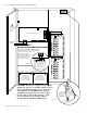
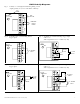
2. Connect unswitched AC power (120VAC 60Hz) to terminals marked [L, N] (Fig. 3, pg. 7). Do not use terminal
marked [G]. Use 14 AWG or larger for all power connections. Secure green wire lead attached to the chassis to
earth ground.
Keep power-limited wiring separate from non power-limited wiring. Minimum 0.25” spacing must be
provided (Fig. 3, pg. 7).
3. Select desired DC output voltage by setting SW1 to the appropriate position on the Maximal3F power supply (Fig. 1a, pg. 6).
Maximal5F power supply is factory set at 12VDC and Maximal7F power supply is factory set at 24VDC.
4. Measure the output voltage of the unit before connecting any devices to ensure proper operation.
Improper or high voltage will damage these devices.
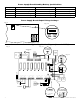
5. Output options (Fig. 2, pg. 6):
The unit will provide either sixteen (16) switched power outputs, sixteen (16) dry form “C” outputs, or any
combination of both switched power and form “C” outputs.
(a) Fail-Safe Switched Power outputs:
For Fail-Safe operation connect the positive (+) input of the access control devices to terminal marked [NC].
Connect the negative (-) input of the access control devices to terminal marked [COM].
(b) Fail-Secure Switched Power outputs:
For Fail-Secure operation connect the positive (+) input of the access control devices to terminal marked [NO].
Connect the negative (-) input of the access control devices to terminal marked [COM].
(c) Form “C” outputs:
When form “C” outputs are desired the corresponding output fuses (1-8) of each ACM8 board must be removed.
6. ACM8 Auxiliary Power outputs (unswitched):
Connect access control devices that require constant power to terminals marked [C] positive (+) and [COM] negative (-).
Outputs can be used to provide power for card readers, keypads etc.
eFlow Auxiliary outputs (unswitched):
For auxiliary device connection this output will not be affected by Low Power Disconnect or Fire Alarm Interface.
Connect device to terminals marked [+ AUX -- ] (Fig. 3, pg. 7).