Series Access Power Controllers Installation Guide Models Include: Maximal11 - Power Supply 1: 12VDC @ 3.5 amp or 24VDC @ 2.7 amp. - Power Supply 2: 12VDC @ 3.5 amp or 24VDC @ 2.7 amp. - Sixteen (16) fuse protected power-limited outputs. Maximal33 - Power Supply 1: 12VDC @ 5.5 amp or 24VDC @ 5.7 amp. - Power Supply 2: 12VDC @ 5.5 amp or 24VDC @ 5.7 amp. - Sixteen (16) fuse protected non power-limited outputs. Maximal55 - Power Supply 1: 12VDC @ 9.5 amp. - Power Supply 2: 12VDC @ 9.5 amp.
Table of Contents: Maximal Series Overview................................................................................................. 3 Maximal Series Configuration Chart................................................................................ 3 Maximal Series Features................................................................................................ 3-4 Maximal Installation Instructions...................................................................................
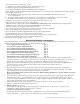
Maximal Series Overview: Maximal Access Power/Controllers distribute and switch power to access control systems and accessories. They convert a 115VAC 60Hz input into sixteen (16) independently controlled 12VDC or 24VDC fuse protected outputs. These Fail-Safe/ Fail-Secure power outputs may be converted to dry form “C” contacts. The outputs are activated by an open collector sink or normally open (NO) dry trigger input from an Access Control System, Keypad, Push Button, REX PIR, etc.
Fire Alarm disconnect input trigger options: a) Normally open (NO) or normally closed (NC) dry trigger input. b) Polarity reversal input from FACP signaling circuit. • Green LED on ACM8 board indicates FACP disconnect is triggered. • FACP output relay indicates that FACP input is triggered (form “C” contact rated @ 1 amp/28VDC not evaluated by UL). • Power supply input options: a) Factory installed power supplies provide common power for both ACM8 boards and all connected access control devices.
(b) Fail-Secure Switched Power outputs: For Fail-Secure operation connect the positive (+) input of the access control devices to terminal marked [NO]. Connect the negative (-) input of the access control devices to terminal marked [COM]. (c) Form “C” outputs: When form “C” outputs are desired the corresponding output fuses (1-8) of each ACM8 board must be removed. 6.
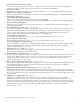
Maintenance: Unit should be tested at least once a year for the proper operation as follows: FACP Supervision: To insure proper connection and operation of the Fire Alarm disconnect hookup. Please follow the appropriate procedure below: Normally Open Input: Placing a short between terminals marked [T] and [+ INP] will trigger the Fire Alarm Disconnect. Remove the short to reset. Normally Closed Input: Remove the wire from terminal marked [INP -- ] will trigger the Fire Alarm Disconnect.
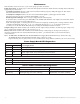
Power Supply Board Terminal Identification: Terminal Legend Function/Description L, G, N Connect 115VAC 60Hz to these terminals: L to hot, N to neutral, G to ground. + DC - Maximal11 - 12VDC @ 3.5 amp or 24VDC @ 2.7 amp to ACM8 boards (power-limited). Maximal33 - 12VDC @ 5.5 amp or 24VDC @ 5.7 amp to ACM8 boards (non power-limited). Maximal55 - 12VDC @ 9.5 amp to ACM8 boards (power-limited). Maximal77 - 24VDC @ 9.7 amp to ACM8 boards (power-limited). Maximal75 - one (1) power supply which is 12VDC @ 9.
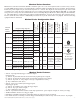
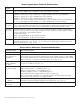
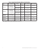
Power Supply Board Stand-by Battery Specifications: Altronix Model Power Supply Board Battery 20 Min. of Backup 4 Hr. of Backup 24 Hr. of Backup 12VDC/40AH* N/A 3.5 amp 0.5 amp Maximal11 AL400ULXB (Refer to Fig. 1a, pg. 9 for Switch [SW1] location and position) 24VDC/40AH* N/A 2.7 amp 0.7 amp 12VDC/40AH* N/A 5.5 amp 5.5 amp 24VDC/40AH* N/A 5.5 amp 0.7 amp 12VDC/12AH 9.0 amp Battery capacity for emergency stand-by at least 20 min N/A 24VDC/12AH 7.7 amp 1.
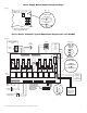
Power Supply Board Output Voltage Settings: Fig. 1 Fig. 1a Opened - 24V Closed - 12V SW1 Switch Detail + DC --- OPEN SWITCH CLOSED SWITCH Maximal11/Maximal33 Power Supply Board Access Power Controller Typical Application Diagram (for each ACM8): Fig. 2 Fig.
Fig. 3 Maximal11 Maximal33 Maximal55 + DC – Tamper Switch + BAT --- Power Supply Board BAT FAIL L G N Line AC FAIL NC C NO NC C NO G Line AC FAIL NC C NO 2.5A 250V NC C NO Neutral 2.5A 250V Ground Lug Optional 12VDC Battery** **24VDC operation: Connect two (2) 12VDC batteries in series 2.5A 250V 2.5A 250V 2.5A 250V 2.5A 250V *12VDC operation: For 12VDC operation only a single battery is needed.
Fig. 4 Maximal77 + DC --- Tamper Switch – BAT + Power Supply Board BAT FAIL L G N Line AC FAIL NC C NO NC C NO Wire Strap (from Enclosure to Door) G Line AC FAIL NC C NO NC C NO Neutral 2.5A 250V 2.5A 250V Ground Lug 2.5A 250V 2.5A 250V 2.5A 250V Ground N 2.5A 250V L 2.5A 250V – BAT + 2.5A 250V Power Supply Board BAT FAIL 115VAC Input 60 Hz.
Fig. 5 Maximal75 – DC + Tamper Switch + BAT --- Power Supply Board BAT FAIL G N Line AC FAIL NC C NO NC C NO Neutral G Line AC FAIL NC C NO 2.5A 250V NC C NO Neutral 2.5A 250V Ground Lug Optional 12VDC Battery** **24VDC operation: Connect two (2) 12VDC batteries in series 2.5A 250V 2.5A 250V 2.5A 250V 2.5A 250V 2.5A 250V *12VDC operation: For 12VDC operation only a single battery is needed.
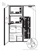
NEC Power-Limited Wiring Requirements for Maximal11: Power-limited and non power-limited circuit wiring must remain separated in the cabinet. All power-limited circuit wiring must remain at least 0.25” away from any non power-limited circuit wiring. Furthermore, all power-limited circuit wiring and non power-limited circuit wiring must enter and exit the cabinet through different conduits. One such example of this is shown below. Your specific application may require different conduit knockouts to be used.
NEC Power-Limited Wiring Requirements for Maximal33 and Maximal55: Power-limited and non power-limited circuit wiring must remain separated in the cabinet. All power-limited circuit wiring must remain at least 0.25” away from any non power-limited circuit wiring. Furthermore, all power-limited circuit wiring and non power-limited circuit wiring must enter and exit the cabinet through different conduits. One such example of this is shown below.
NEC Power-Limited Wiring Requirements for Maximal77: Power-limited and non power-limited circuit wiring must remain separated in the cabinet. All power-limited circuit wiring must remain at least 0.25” away from any non power-limited circuit wiring. Furthermore, all power-limited circuit wiring and non power-limited circuit wiring must enter and exit the cabinet through different conduits. One such example of this is shown below. Your specific application may require different conduit knockouts to be used.
NEC Power-Limited Wiring Requirements for Maximal75: Power-limited and non power-limited circuit wiring must remain separated in the cabinet. All power-limited circuit wiring must remain at least 0.25” away from any non power-limited circuit wiring. Furthermore, all power-limited circuit wiring and non power-limited circuit wiring must enter and exit the cabinet through different conduits. One such example of this is shown below. Your specific application may require different conduit knockouts to be used.
FACP/Optional Power Supply Hook-up Diagrams: Fig. 10 Optional hook-up using two (2) isolated power supply inputs (Only applicable on Maximal11): Fig.
Enclosure Dimensions: 26”H x 19”W x 6.25”D 1‘7" 2.00" 7.00" 4.00" 4.00" 2.00" 6.25" TOP 1‘7" 1.25" 0.85" 8.90" 8.40" 1.25" 0.85" 1.50" 1.50" 1.50" 5.00" 8.50" 7.00" 7.50" 7.50" 8‘5" 2‘2" 2‘2" LEFT 2‘2" RIGHT 7.00" 10.0" 1.00" 0.85" 8.90" 8.40" 0.85" BOTTOM 1’7" - 18 - 2.00" 1.00" 1.25" 6.25" 4.00" 2.
Notes: Maximal11/Maximal33/Maximal55/Maximal77/Maximal75 Access Power Controllers (Fused) - 19 -
Notes: Altronix is not responsible for any typographical errors. 140 58th Street, Brooklyn, New York 11220 USA, 718-567-8181, fax: 718-567-9056 web site: www.altronix.com, e-mail: info@altronix.com, Lifetime Warranty, Made in U.S.A.