Series Access Power Controllers Installation Guide Models Include: Maximal3 - 12VDC @ 5 amp or 24VDC @ 5.4 amp. - Sixteen (16) fuse protected non power-limited outputs. Maximal5 - 12VDC @ 9 amp. - Sixteen (16) fuse protected non power-limited outputs. Maximal7 - 24VDC @ 9.4 amp. - Sixteen (16) fuse protected non power-limited outputs. Altronix Corp. 140 58th St. Brooklyn, NY Rev. SF110912 More than just power.
Table of Contents: Maximal Series Overview................................................................................................. 3 Maximal Series Configuration Chart................................................................................ 3 Maximal Series Features................................................................................................... 3 Maximal Installation Instructions...................................................................................
Maximal Series Overview: Maximal Access Power/Controllers distribute and switch power to access control systems and accessories. They convert a 115VAC 60Hz input into sixteen (16) independently controlled 12VDC or 24VDC fuse protected outputs. These Fail-Safe/ Fail-Secure power outputs may be converted to dry form “C” contacts. The outputs are activated by an open collector sink or normally open (NO) dry trigger input from an Access Control System, Keypad, Push Button, REX PIR, etc.
• Enclosure accommodates up to four (4) 12VDC/12AH batteries. Enclosure dimensions (HxWxD): 26” (660.4mm) x 19” (482.6mm) x 6.25” (158.75mm) Maxim Installation Instructions: Wiring methods shall be in accordance with the National Electrical Code/NFPA 70/ANSI, and with all local codes and authorities having jurisdiction. Product is intended for indoor use only. Power Supply Board LED Diagnostics (pg. 5) Access Power Controller LED Diagnostics (pg. 6) Power Supply Board Terminal Identification (pg.
(b) Normally Closed [NC] input: For non-latching hook-up refer to (Fig. 11, pg. 14). For latching hook-up refer to (Fig. 12, pg. 14). (c) FACP Signaling Circuit input trigger: Connect the positive (+) and negative (-) from the FACP signaling circuit output to the terminals marked [+ INP -]. Connect the FACP EOL to the terminals marked [+ RET -] (polarity is referenced in an alarm condition). Jumper J3 must be cut (Fig. 8, pg. 14). 9. FACP Dry form “C” output (Fig. 2a, pg.
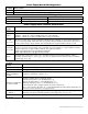
Power Supply Board LED Diagnostics: Red (Bat) ON OFF Battery Status Normal operating condition. Battery fail/low battery. Access Power Controller LED Diagnostics: LED LED 1- LED 8 (Red) Trg (Green) ON OFF Output relay(s) energized. Output relay(s) de-energized. FACP input triggered (alarm condition). FACP normal (non-alarm condition). Power Supply Board Terminal Identification: Terminal Legend L, G, N Function/Description Connect 115VAC 60Hz to these terminals: L to hot, N to neutral.
Power Supply Board Stand-by Battery Specifications: Altronix Model: Power Supply Board Battery 20 Min. of Backup 4 hr. of Backup 24 hr. of Backup Maximal3 AL600ULXB (Refer to Fig. 1a, pg. 7 for Switch [SW1] location and position) 12VDC/40AH* N/A 5.0 amp N/A 24VDC/40AH* N/A 5.4 amp 0.7 amp Maximal5 AL1012ULXB (Factory set at 12VDC) 12VDC/12AH 9.0 amp Maximal7 AL1024ULXB2 (Factory set at 24VDC) 24VDC/12AH 24VDC/65AH* 7.7 amp Battery capacity for emergency stand-by at least 20 min. 1.
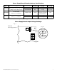
Access Power Controller Typical Application Diagram (for each ACM8): Fig. 2 Fig. 2a KEYPAD FACP C FACP Dry Form "C" Output (Fire Alarm Control Panel) NO + NC --- OUTPUT RELAY PUSH BUTTON F1 F2 F3 TRG IN GND IN GND IN GND IN GND 5 6 7 8 F4 F5 F7 F8 SW5 F6 NO C NC FACP IN GND IN GND IN GND IN GND 1 2 3 4 + INP --- T + RET INTERFACE J3 2.5A 250V NO C NC FACP ACCESS CONTROL PANEL 2.5A 250V 2.5A 250V 2.5A 250V 2.5A 250V 2.5A 250V 2.5A 250V SW1-SW8 2.
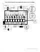
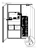
Fig. 3 Maximal3 Maximal5 Tamper Switch Wire Strap (from Enclosure to Door) + DC --- --- DC + Maximal5 + BAT --- Power Supply Board G BAT FAIL N NO C NC NO C NC AC FAIL 2.5A 250V L Line Neutral 2.5A 250V 115VAC Input 60 Hz. 2.5A 250V 2.5A 250V 2.5A 250V Earth Ground 2.5A 250V 2.5A 250V 2.5A 250V Optional 12VDC Battery* 2.5A 250V 2.5A 250V 2.5A 250V 2.5A 250V 2.5A 250V Fig. 3a + BAT --- 2.
Fig. 4 Maximal7 + DC --- Tamper Switch 15A 32V Power Supply Board Line N AC FAIL NC C NO NC C NO AC DELAY Neutral 2.5A 250V 115VAC Input 60 Hz. G 2.5A 250V 5A 250V BAT FAIL L DC --- BAT + 15 AC 2.5A 250V 2.5A 250V 2.5A 250V 2.5A 250V 2.5A 250V 2.5A 250V Earth Ground Optional 12VDC Battery** 2.5A 250V 2.5A 250V 2.5A 250V 2.5A 250V 2.5A 250V 2.5A 250V 2.5A 250V 2.5A 250V Optional 12VDC Battery** **24VDC operation: Connect two (2) 12VDC batteries in series Fig.
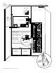
NEC Power-Limited Wiring Requirements for Maximal3: Power-limited and non power-limited circuit wiring must remain separated in the cabinet. All power-limited circuit wiring must remain at least 0.25” away from any non power-limited circuit wiring. Furthermore, all power-limited circuit wiring and non power-limited circuit wiring must enter and exit the cabinet through different conduits. One such example of this is shown below. Your specific application may require different conduit knockouts to be used.
NEC Power-Limited Wiring Requirements for Maximal5: Power-limited and non power-limited circuit wiring must remain separated in the cabinet. All power-limited circuit wiring must remain at least 0.25” away from any non power-limited circuit wiring. Furthermore, all power-limited circuit wiring and non power-limited circuit wiring must enter and exit the cabinet through different conduits. One such example of this is shown below. Your specific application may require different conduit knockouts to be used.
NEC Power-Limited Wiring Requirements for Maximal7: Power-limited and non power-limited circuit wiring must remain separated in the cabinet. All power-limited circuit wiring must remain at least 0.25” away from any non power-limited circuit wiring. Furthermore, all power-limited circuit wiring and non power-limited circuit wiring must enter and exit the cabinet through different conduits. One such example of this is shown below. Your specific application may require different conduit knockouts to be used.
FACP Hook-up Diagrams: Fig. 8 Polarity reversal input from FACP signaling circuit output (polarity is referenced in alarm condition): FACP SIGNAL CIRCUIT OUTPUT EOL -+ FROM FACP SIGNAL OUTPUT CIRCUIT NO C NC FACP INTERFACE CUT JUMPER J3 NO C NC FACP INTERFACE NC N.O. TRIGGER INPUT JUMPER N.C. RESET SWITCH NO C Fig. 11 Normally Closed - Non-Latching FACP trigger input: - 14 - Fig. 10 Normally Open FACP Latching trigger input with reset: (This output has not been evaluated by UL) N.O.
Enclosure Dimensions (HxWxD): 26” (660.4mm) x 19” (482.6mm) x 6.25” (158.75mm) 19” (482.6mm) 2” (50.8mm) 4” (101.6mm) 7” (177.8mm) 4” (101.6mm) 2” (50.8mm) 6.25” (158.75mm) TOP 1.25” (31.75mm) 0.85” (21.59mm) 19” (482.6mm) 8.9” (226.06mm) 1.25” (31.75mm) 0.85” (21.59mm) 8.4” (213.36mm) 1.5” (38.1mm) 1.5” (38.1mm) 1.5” (38.1mm) 5” (127mm) 1.25” (31.75mm) 8.5” (215.9mm) 7” (177.8mm) 7.5” (190.5mm) 7.5” (190.5mm) 26” (660.4mm) 8.5” (215.9mm) 26” (660.4mm) 26” (660.
Notes: Altronix is not responsible for any typographical errors. 140 58th Street, Brooklyn, New York 11220 USA, 718-567-8181, fax: 718-567-9056 web site: www.altronix.com, e-mail: info@altronix.com, Lifetime Warranty, Made in U.S.A.