
Installation Guide


Maximal3F/Maximal5F/Maximal7F Access Power Controllers (Fused) - 5 -
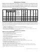
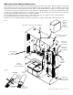
Battery Test: Under normal load conditions check that the battery is fully charged, check specified voltage at the battery terminals
and at the board terminals marked [+ BAT -] to ensure that there is no break in the battery connection wires.
Note: Maximum charge current is 1.54 amp.
Expected battery life is 5 years; however, it is recommended to change batteries within 4 years or less if necessary.
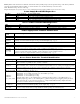
Power Supply Board LED Diagnostics:
Red (DC) Green (AC/AC1) Power Supply Status
ON ON Normal operating condition.
ON OFF Loss of AC. Stand-by battery supplying power.
OFF ON No DC output.
OFF OFF Loss of AC. Discharged or no stand-by battery. No DC output.
Access Power Controller LED Diagnostics:
LED ON OFF
LED 1- LED 8 (Red) Output relay(s) energized. Output relay(s) de-energized.
Trg (Green) FACP input triggered (alarm condition). FACP normal (non-alarm condition).
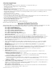
Power Supply Board Terminal Identification:
Terminal
Legend
Function/Description
L, N Connect 120VAC 60Hz to these terminals: L to hot, N to neutral. Do not use terminal marked [G]
+ DC – Factory connected to ACM8 board.
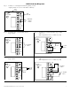
Trigger EOL
Supervised
Fire Alarm Interface trigger input from a short or FACP. Trigger inputs can be normally open,
normally closed from an FACP output circuit (power-limited input) (Fig. 3, pg. 7).
NO, GND
RESET
FACP interface latching or non-latching (power-limited) (Fig. 3, pg. 7).
+ AUX – Auxiliary Power-Limited output rated @ 1 amp (unswitched) (power-limited output) (Fig. 3, pg. 7).
AC FAIL
NC, C, NO
Indicates loss of AC power, e.g. connect to audible device or alarm panel. Relay normally energized
when AC power is present. Contact rating 1 amp @ 30VDC (power-limited) (Fig. 3, pg. 7).
BAT FAIL
NC, C, NO
Indicates low battery condition, e.g. connect to alarm panel. Relay normally energized when DC power
is present. Contact rating 1 amp @ 30VDC. A removed battery is reported within 5 minutes.
Battery reconnection is reported within 1 minute (power-limited) (Fig. 3, pg. 7).
+ BAT – Stand-by battery connections. Maximum charge current 1.54 amp (non power-limited) (Fig. 3, pg. 7).
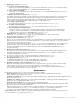
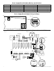
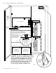
Access Power Controller Terminal Identification:
Terminal Legend Function/Description
-- Power +
12VDC or 24VDC from power supply/charger (factory connected).
These terminals are paralleled to the - Control + terminals.
-- Control +
These terminals are paralleled to the - Power + terminals.
These terminals can be connected to an external Listed power-limited access control power supply to provide
isolated operating power for the devices (Not evaluated by UL) (jumpers J1 and J2 must be removed).
TRIGGER INPUT1 -
INPUT 8 IN, GND
From normally open and/or open collector sink trigger inputs
(request to exit buttons, exit pir’s, etc.)
OUTPUT 1-
OUTPUT 8
NC, C, NO, COM
12VDC to 24VDC trigger controlled outputs are rated at 2.5 amp.
Maximal3F - 10.0-13.2VDC @ 4.6 amp or 20.19-26.4VDC @ 5.2 amp.
Maximal5F - 10.03-13.2VDC @ 8.6 amp.
Maximal7F - 20.17-26.4VDC @ 9.2 amp.
Fail-Safe [NC positive (+) & COM Negative (-)], Fail-Secure [NO positive (+) & COM Negative (-)],
Auxiliary output [C positive (+) & COM Negative (-)] (When using AC power supplies polarity needs not
to be observed), NC, C, NO convert to dry form “C” 5 amp 24VAC/VDC rated dry outputs when fuses
are removed. Contacts shown in a non-triggered state.
FACP INTERFACE
T, + INPUT --
Fire Alarm Interface trigger input from FACP. Trigger inputs can be normally open,
normally closed from an FACP signaling circuit output (Figs. 5-9, pg. 9).
FACP INTERFACE
NC, C, NO
Form “C” relay contact rated @ 1 amp 28VDC for alarm reporting (not evaluated by UL).