Access Power Controllers with Power Supplies Installation Guide for models: Maximal3F - 12VDC @ 4.6 amp or 24VDC @ 5.2 amp. - Sixteen (16) fuse protected non power-limited outputs. Maximal5F - 12VDC @ 8.6 amp. - Sixteen (16) fuse protected non power-limited outputs. Maximal7F - 24VDC @ 9.2 amp. - Sixteen (16) fuse protected non power-limited outputs. Altronix Corp. 140 58th St. Brooklyn, NY Rev. SFF051313 More than just power.™ Installing Company: ______________________ Service Rep.
MaximalF Series Overview: MaximalF Access Power/Controllers distribute and switch power to access control systems and accessories. They convert a 120VAC 60Hz input into sixteen (16) independently controlled 12VDC or 24VDC fuse protected outputs. These Fail-Safe/Fail-Secure power outputs may be converted to dry form “C” contacts. The outputs are activated by an open collector sink or normally open (NO) dry trigger input from an Access Control System, Keypad, Push Button, REX PIR, etc.
eFlow Power Supply/Charger: • • • • • • • • Input: 120VAC, 60Hz. For output voltage and supply current refer to MaximalF series Configuration Chart, pg. 2. Auxiliary power-limited output rated @ 1 amp (unswitched). Overvoltage Protection. Built-in charger for sealed lead acid or gel type batteries. Maximum charge current 1.54 amp. Automatic switch over to stand-by battery when AC fails. Transfer to stand-by battery power is instantaneous with no interruption.
Input trigger options (Fig. 2, pg. 6): (a) Normally Open [NO] input trigger: Inputs 1-8 are activated by normally open or open collector sink inputs. Connect access control panel outputs, keypads, push buttons, REX PIRs, etc. to terminals marked [IN] and [GND]. (b) Open Collector Sink inputs: Connect the access control panel open collector sink positive (+) to terminals marked [IN] and the negative (-) to terminals marked [GND]. 8. ACM8 Fire Alarm Interface options (Figs. 5-9, pg.
Battery Test: Under normal load conditions check that the battery is fully charged, check specified voltage at the battery terminals and at the board terminals marked [+ BAT -] to ensure that there is no break in the battery connection wires. Note: Maximum charge current is 1.54 amp. Expected battery life is 5 years; however, it is recommended to change batteries within 4 years or less if necessary.
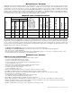
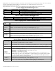
Power Supply Board Stand-by Battery Specifications: Battery Maximal3F Maximal5F 7AH 10 Mins./6 amp 5 Mins./10 amp 12AH 30 Mins./6 amp* 30 Mins./10 amp* 40AH Over 4 Hours/6 amp* Over 2 Hours/10 amp* 65AH Over 4 Hours/6 amp* Over 4 Hours/10 amp* *Only these configurations can be utilized in ULC-S319 installations. Maximal7F 5 Mins./10 amp 30 Mins./10 amp* Over 2 Hours/10 amp* Over 4 Hours/10 amp* Power Supply Board Output Voltage Settings: Fig. 1a OFF - 24V ON - 12V ON ON Fig.
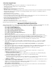
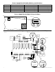
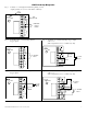
Fig. 3. Maximal3F, Maximal5F, and Maximal7F. --- DC + J2 J1 1 LED7 LED6 NC C NO COM NC C NO COM OUTPUT 3 OUTPUT 4 LED5 LED4 NC C NO COM NC C NO COM OUTPUT 1 OUTPUT 2 LED3 LED2 F2 LED1 F1 CAUTION: When power supply board is set for 12VDC use only one (1) 12VDC stand-by battery. Keep power-limited wiring separate from non power-limited. Use minimum 0.25" spacing. 12AH Rechargeable batteries are the largest batteries that can fit in this enclosure.
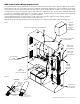
NEC Power-Limited Wiring Requirements: Power-limited and non power-limited circuit wiring must remain separated in the cabinet. All power-limited circuit wiring must remain at least 0.25” away from any non power-limited circuit wiring. Furthermore, all power-limited circuit wiring and non power-limited circuit wiring must enter and exit the cabinet through different conduits. One such example of this is shown below. Your specific application may require different conduit knockouts to be used.
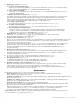
Fig. 5 FACP Hook-Up Diagrams: Polarity reversal input from FACP signaling circuit output (polarity is referenced in alarm condition): CUT JUMPER INTERFACE FACP OUTPUT EOL -- FROM FACP OUTPUT + CIRCUIT NO C NC FACP TRG Fig. 6 Normally Open - Non-Latching FACP Fig. 7 Normally Open FACP Latching trigger input trigger input: with reset: (This output has not been evaluated by UL) INTERFACE TRG N.O. TRIGGER INPUT NC N.O. TRIGGER INPUT N.C. RESET SWITCH JUMPER NO C NO C NC FACP TRG Fig.
Notes: - 10 - Maximal3F/Maximal5F/Maximal7F Access Power Controllers (Fused)
Notes: Maximal3F/Maximal5F/Maximal7F Access Power Controllers (Fused) - 11 -
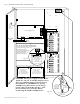
Enclosure Dimensions (H x W x D approximate): 26” x 19” x 6.25” (660.4mm x 482.6mm x 158.75mm) 19” (482.6mm) 2” (50.8mm) 4” (101.6mm) 7” (177.8mm) 4” (101.6mm) 2” (50.8mm) 6.25” (158.75mm) TOP 1.25” (31.75mm) 0.85” (21.59mm) 19” (482.6mm) 8.9” (226.06mm) 1.25” (31.75mm) 0.85” (21.59mm) 8.4” (213.36mm) 1.5” (38.1mm) 1.5” (38.1mm) 1.5” (38.1mm) 5” (127mm) 8.5” (215.9mm) 7” (177.8mm) 7.5” (190.5mm) 7.5” (190.5mm) 26” (660.4mm) 8.5” (215.9mm) 26” (660.4mm) 26” (660.