
Installation Guide


Maximal3FD/Maximal5FD/Maximal7FD Access Power Controllers (PTC) - 5 -
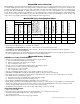
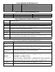
Power Supply Board LED Diagnostics:
Red (DC) Green (AC/AC1) Power Supply Status
ON ON Normal operating condition.
ON OFF Loss of AC. Stand-by battery supplying power.
OFF ON No DC output.
OFF OFF Loss of AC. Discharged or no stand-by battery. No DC output.
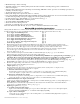
Access Power Controller LED Diagnostics:
LED ON OFF
LED 1- LED 8 (Red) Output relay(s) energized. Output relay(s) de-energized.
Trg (Green) FACP input triggered (alarm condition). FACP normal (non-alarm condition).
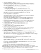
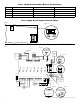
Power Supply Board Terminal Identification:
Terminal
Legend
Function/Description
L, N Connect 120VAC 60Hz to these terminals: L to hot, N to neutral. Do not use terminal marked [G].
+ DC – Factory connected to ACM8CB board.
Trigger EOL
Supervised
Fire Alarm Interface trigger input from a short or FACP. Trigger inputs can be normally open,
normally closed from an FACP output circuit (power-limited input).
NO, GND
RESET
FACP interface latching or non-latching (power-limited).
+ AUX – Auxiliary Power-Limited output rated @ 1 amp (unswitched) (power-limited output).
AC Fail
NC, C, NO
Indicates loss of AC power, e.g. connect to audible device or alarm panel. Relay normally energized
when AC power is present. Contact rating 1 amp @ 30VDC (power-limited).
Bat Fail
NC, C, NO
Indicates low battery condition, e.g. connect to alarm panel. Relay normally energized when DC power
is present. Contact rating 1 amp @ 30VDC. A removed battery is reported within 5 minutes.
Battery reconnection is reported within 1 minute (power-limited).
– BAT + Stand-by battery connections. Maximum charge current 1.54 amp (non power-limited).
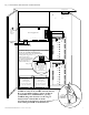
Access Power Controller Terminal Identification:
Terminal Legend Function/Description
-- Power +
12VDC or 24VDC from power supply/charger (factory connected).
These terminals are paralleled to the - Control + terminals.
-- Control +
These terminals are paralleled to the - Power + terminals. They can be connected to an external
Listed power-limited access control power supply to provide isolated operating power for the
devices (Not evaluated by UL) (jumpers J1 and J2 must be removed).
TRIGGER
INPUT 1-INPUT 8
IN, GND
From normally open and/or open collector sink trigger inputs
(request to exit buttons, exit pir’s, etc.)
OUTPUT 1-
OUTPUT 8
NC, C, NO, COM
12VDC to 24VDC trigger controlled outputs are rated at 2 amp.
Maximal3FD - 9.7-13.2VDC @ 4.6 amp or 19.8-26.4VDC @ 5.2 amp.
Maximal5FD - 9.7-13.2VDC @ 8.6 amp.
Maximal7FD - 19.8-26.4VDC @ 9.2 amp.
Fail-Safe [NC positive (+) and COM Negative (-)], Fail-Secure [NO positive (+) and COM
Negative (-)], Auxiliary output [C positive (+) and COM Negative (-)] (When using AC power
supplies polarity needs not to be observed). Contacts shown in a non-triggered state.
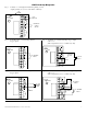
FACP INTERFACE
T, + INPUT --
Fire Alarm Interface trigger input from FACP. Trigger inputs can be normally open,
normally closed from an FACP signaling circuit output (Figs. 5-9, pg. 9).
FACP INTERFACE
NC, C, NO
Form “C” relay contact rated @ 1 amp 28VDC for alarm reporting (not evaluated by UL).