
Installation Guide

- 4 - Maximal3F/Maximal5F/Maximal7F Access Power Controllers (Fused)
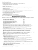
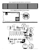
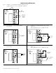
7. Input trigger options (Fig. 2, pg. 6):
(a) Normally Open [NO] input trigger:
Inputs 1-8 are activated by normally open or open collector sink inputs. Connect access control panel outputs,
keypads, push buttons, REX PIRs, etc. to terminals marked [IN] and [GND].
(b) Open Collector Sink inputs:
Connect the access control panel open collector sink positive (+) to terminals marked [IN] and the negative (-)
to terminals marked [GND].
8. ACM8 Fire Alarm Interface options (Figs. 5-9, pg. 9):
A normally closed [NC] or normally open [NO] input trigger from a fire alarm control panel or a polarity reversal
input from an FACP signaling circuit will affect selected outputs. To enable FACP Disconnect for an output,
turn the corresponding switch(es) [SW1-SW8] OFF on each ACM8 board. To disable FACP disconnect for an
output, turn the corresponding switch(es) [SW1-SW8] ON on each ACM8 board.
(a) Normally Open [NO] input:
For non-latching hook-up refer to (Fig. 6, pg. 9). For latching hook-up refer to (Fig. 7, pg. 9).
(b) Normally Closed [NC] input:
For non-latching hook-up refer to (Fig. 8, pg. 9). For latching hook-up refer to (Fig. 9, pg. 9).
(c) FACP Signaling Circuit input trigger:
Connect the positive (+) and negative (-) from the FACP signaling circuit output to the terminals marked
[+ INP -]. Connect the FACP EOL to the terminals marked [+ RET -] (polarity is referenced in an alarm
condition). Jumper located next to TRG LED must be cut (Fig. 5, pg. 9).
9. FACP Dry form “C” output (Fig. 2a, pg. 6) (Not evaluated by UL):
FACP form “C” contacts can be use to trigger reporting or signaling devices. These contact switch
upon a fire alarm input trigger to the ACM8 boards.
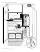
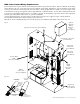
10. Stand-by Battery Connections (Figs. 3, pg. 7):
For U.S. Access Control applications batteries are optional. Batteries are required for Canadian installations (ULC-S319).
When batteries are not used, a loss of AC will result in the loss of output voltage. When the use of stand-by batteries
is desired, they must be lead acid or gel type.
Connect battery to terminals marked [-- BAT + ] (Fig. 3, pg. 7). Use two (2) 12VDC batteries connected in series for
24VDC operation (battery leads included). Use batteries - Casil CL1270 (12V/7AH), CL12120 (12V/12AH),
CL12400 (12V/40AH), CL12650 (12V/65AH) batteries or UL recognized BAZR2 and BAZR8 batteries of
an appropriate rating.
11. Battery and AC Supervision outputs (Fig. 3, pg. 7):
It is required to connect supervisory trouble reporting devices to outputs marked [AC Fail, BAT Fail] supervisory
relay outputs marked [NC, C, NO] to appropriate visual notification devices. Use 22 AWG to 18 AWG for
AC Fail & Low/No Battery reporting.
12. To delay AC reporting for 2 hrs., set dip switch [AC Delay] to OFF position (Fig. 3, pg. 7).
To delay AC reporting for 1 min., set dip switch [AC Delay] to ON position (Fig. 3, pg. 7).
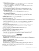
13. Fire Alarm Disconnect (Fig. 3, pg. 7):
To enable Fire Alarm Disconnect set dip switch [Shutdown] to ON position.
To disable Fire Alarm Disconnect set dip switch [Shutdown] to OFF position.
14. Installation of tamper switch (Not Included) (Fig. 3b, pg. 7):
Mount UL Listed tamper switch (Sentrol model 3012 or equivalent) at the top of the enclosure. Slide the tamper
switch bracket onto the edge of the enclosure approximately 2” from the right side (Fig. 3b, pg. 7).
Connect tamper switch wiring to the Access Control Panel input or the appropriate UL Listed reporting device.
To activate alarm signal, open the door of the enclosure.
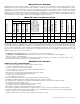
Maintenance:
Unit should be tested at least once a year for the proper operation as follows:
FACP Supervision: To ensure proper connection and operation of the Fire Alarm disconnect hookup.
Please follow the appropriate procedure below:
Normally Open Input: Placing a short between terminals marked [T] and [+ INP] will trigger the Fire Alarm Disconnect.
Remove the short to reset.
Normally Closed Input: Removing the wire from terminal marked [INP -- ] will trigger the Fire Alarm Disconnect.
Replace the wire to terminal marked [INP -- ] to reset.
FACP Signal Circuit Input: It is necessary to trigger the Fire Alarm System.
In all of the above scenarios the green TRG LED of the ACM8s will illuminate. All outputs selected for Fire Alarm
Disconnect will activate releasing locking devices.
Note: All outputs [OUT 1 - OUT 8] must be in a normal (de-energized) condition prior to testing. When the unit is
configured for Normally Open (Fig. 7, pg. 9) or Normally Closed (Fig. 9, pg. 9) latching operation it is
necessary to reset the Fire Alarm Disconnect by activating the Normally Closed reset switch.
Output Voltage Test: Under normal load conditions, the DC output voltage should be checked for proper voltage level
(refer to MaximalF series Configuration Chart, pg. 2).