
Installation Guide

Maximal3D/Maximal5D/Maximal7D Access Power Controllers (PTC) Installation Guide - 5 -
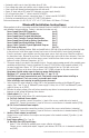
(b) Open Collector Sink inputs:
Connect the access control panel open collector sink positive (+) to terminals marked [IN] and the
negative (–) to terminals marked [GND].
8. Fire Alarm Interface options
(Figs. 8-12, pg. 14):
A normally closed [NC] or normally open [NO] input trigger from a fire alarm control panel or a polarity
reversal input from an FACP signaling circuit will affect selected outputs.
To enable FACP Disconnect for an output turn the corresponding switch(es) [SW1-SW8] OFF on each
ACM8CB board. To disable FACP disconnect for an output turn the corresponding switch(es) [SW1-SW8]
ON on each ACM8CB board.
(a) Normally Open [NO] input:
For non-latching hook-up refer to
Fig. 9, pg. 14. For latching hook-up refer to Fig. 10, pg. 14.
(b) Normally Closed [NC] input:
For non-latching hook-up refer to
Fig. 11, pg. 14. For latching hook-up refer to Fig. 12, pg. 14.
(c) FACP Signaling Circuit input trigger:
Connect the positive (+) and negative (–) from the FACP signaling circuit output to the terminals marked
[+ INP –]. Connect the FACP EOL to the terminals marked [+ RET –] (polarity is referenced in an alarm
condition). Jumper located next to TRG LED must be cut
(Fig. 2a, pg. 7 and Fig. 8, pg. 14).
9. FACP Dry form “C” output
(Fig. 2b, pg. 7):
FACP form “C” contacts can be use to trigger reporting or signaling devices.
These contact switch upon a fire alarm input trigger to the ACM8CB boards.
10. Stand-by Battery Connections
(Figs. 3-7, pgs. 9-13):
For Access Control applications batteries are optional. If batteries are not used a loss of AC will result in
the loss of output voltage. Batteries must be lead acid or gel type. Connect one (1) 12VDC battery to the
terminals marked [+ BAT –] for 12VDC operation
(Fig. 3a, pg. 9). Use two (2) 12VDC batteries wired in
series for 24VDC operation.
11. Battery and AC Supervision outputs
(Figs. 3-4, pgs. 9-10):
It is required to connect supervisory trouble reporting devices to outputs marked [AC Fail, BAT FAIL]
supervisory relay outputs marked [NC, C, NO] to appropriate visual notification devices.
Use 22 AWG to 18 AWG for AC Fail & Low/No Battery reporting.
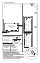
12. Installation of tamper switch (Not Included)
(Figs. 3b-4a, pgs. 9-10):
Mount UL Listed tamper switch (Altronix Model TS112 or equivalent) at the top of the enclosure. Slide the
tamper switch bracket onto the edge of the enclosure approximately 2” from the right side
(Figs. 3b and 4a,
pgs. 9-10)
. Connect tamper switch wiring to the Access Control Panel input or the appropriate UL Listed
reporting device. To activate alarm signal open the door of the enclosure.