
Installation Guide


Maximal3D/Maximal5D/Maximal7D Access Power Controllers (PTC) Installation Guide - 11 -
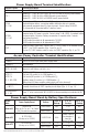
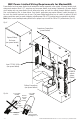
NEC Power-Limited Wiring Requirements for Maximal3D:
Power-limited and non power-limited circuit wiring must remain separated in the cabinet. All power-limited circuit
wiring must remain at least 0.25” away from any non power-limited circuit wiring. Furthermore, all power-limited
circuit wiring and non power-limited circuit wiring must enter and exit the cabinet through different conduits.
One such example of this is shown below. Your specific application may require different conduit knockouts to
be used. Any conduit knockouts may be used. For power- limited applications use of conduit is optional. All field
wiring connections must be made employing suitable gauge CM or FPL jacketed wire (or equivalent substitute).
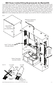
Note: Refer to wire handling drawing below for the proper way to install the CM or FPL jacketed wire
(Fig. 5a).
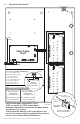
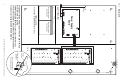
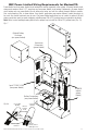
Fig. 5
Supervisory Connections
(power-limited)
Input 115VAC, 60Hz
(non power-limited)
Optional Battery
Enclosure
(non power-limited)
Battery Connections
(non power-limited)
ACM8CB
outputs
(power-
limited)
External
Jacketed
Shield
Incorrect Wire
Handling
Correct Wire
Handling
Pull back
external jacketed
shield approx. 1/2”.
Wire
Insulation
Solid Copper
Conductors
Fig. 5a