
Installation Instructions

MaximalRV Rack Access Power Controllers (Fused) Installation Guide - 5 -
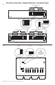
17. Output connections:
Connect the devices to be powered to the removable terminals marked [– OUT1 +] to [– OUT8 +] for
Maximal1RHV and Maximal3RHV. For Maximal1RV, Maximal3RV, and Maximal33RV connect devices
to the second set of terminals marked [– OUT1 +] to [– OUT8 +] (Fig. 15c, pg. 12).
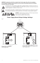
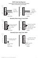
18. Fire Alarm Interface connection options:
a. Connect the FACP trigger input to the removable terminals marked FACP1 and FACP2. When using the
polarity reversal from an FACP signaling circuit, connect the negative [–] to the terminal marked FACP1
and the positive [+] to the terminal marked FACP2 (polarity is in alarm condition)
(Rack Mechanical Drawing and Dimensions pg. 12).
b. For a latching fire alarm interface connect a normally [NO] reset switch to the removable terminals
marked [REST] and [GND] (Figs. 6-11, pg. 9).
19. Set the power disconnect circuit breaker to the ON position (Fig. 15a, pg. 12).
Maintenance:
Unit should be tested at least once a year for the proper operation as follows:
Output Voltage Test: Under normal load conditions the DC output voltage should be checked for proper voltage
level (Output Voltage and Stand-by Specification Charts, pg. 5).
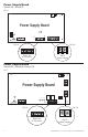
Battery Test: Under normal load conditions check that the battery is fully charged, check specified voltage at
the battery terminals and at the board terminals marked [– BAT +] to ensure that there is no break in the battery
connection wires.
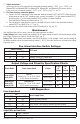
Fire Alarm Interface Switch Settings:
Switch Position
FACP Input
SW1 SW2
OFF OFf FACP Signal Circuit (Polarity Reversal).
ON ON Normally Closed [NC] Trigger Input.
ON OFF Normally Open [NO] Trigger Input.
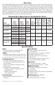
Output Voltage and Stand-by Specification Charts:
Altronix Model Power Supply Board Battery
20 Min.
of
Backup
4 Hr.
of
Backup
24 Hr.
of
Backup
Maximal1RHV
Maximal1RV
OLS120
(Refer to Fig. 1a, pg. 6 for Switch
[SW1] location and position)
12VDC/40AH* N/A 3.5A 0.5A
24VDC/40AH* N/A 2.7A 0.7A
Maximal3RHV
Maximal3RV
Maximal33RV
AL600XB220
(Refer to Fig. 1a, pg. 6 for Switch
[SW1] location and position)
12VDC/40AH* N/A 5.5A 5.5A
24VDC/40AH* N/A 5.5A 0.7A
LED Diagnostics:
Power Supply Board
LED
Power Supply Status
Red (DC) Green (AC)
ON ON Normal operating condition.
ON OFF Loss of AC. Stand-by battery is supplying power.
OFF ON No DC output. Short circuit or thermal overload condition.
OFF OFF No DC output. Loss of AC. Discharged battery.
Output LEDs on Front Panel
ON Output is triggered.
Blinking FACP disconnect.