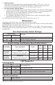
Maximal RV Series Rack Mount Access Power Controllers (fused) Models Include: Maximal1RHV Maximal1RV Maximal3RHV Maximal3RV - 12VDC @ 4A or 24VDC @ 3A. - Eight (8) fuse protected outputs. - 12VDC or 24VDC @ 6A. - Eight (8) fuse protected outputs. - 12VDC @ 4A or 24VDC @ 3A. - Sixteen (16) fuse protected outputs. - 12VDC or 24VDC @ 6A. - Sixteen (16)) fuse protected outputs. Maximal33RV - 12VDC or 24VDC @ 12A. - Sixteen (16) fuse protected outputs. Installation Guide Rev.
Table of Contents: Overview. . . . . . . . . . . . . . . . . . . . . . . . . . . . . . . . . . . . . . . . . . . . . . . . . . . . . . . . . . . . . . . . . . pg. 3 Maximal Rack Mount Series Configuration Chart. . . . . . . . . . . . . . . . . . . . . . . . . . . . . . . . . . . pg. 3 Specifications. . . . . . . . . . . . . . . . . . . . . . . . . . . . . . . . . . . . . . . . . . . . . . . . . . . . . . . . . . . . . . pg. 3 Installation Instructions. . . . . . . . . . . . . . . . . . . . . . . . . . . . .
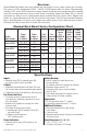
Overview: Altronix Maximal Rack Mount Series units distribute and switch power to access control systems and accessories. They convert a 220VAC (working range 198VAC - 256VAC), 50/60Hz input into eight (8) or sixteen (16) independently controlled 12VDC and/or 24VDC fuse protected outputs. Outputs are activated by an normally open (NO) or normally closed (NC) dry trigger input from an Access Control System, Card Reader, Keypad, Push Button, PIR, etc.
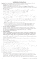
Installation Instructions: Important: Adjust output voltages and Fire Alarm Interface configuration before installing unit in the rack. 1. Separate bottom and top of the rack mount chassis by removing six (6) screws (Rack Mechanical Drawing and Dimensions, pg. 12). CAUTION: Do not touch exposed metal parts. Shut branch circuit power before installing or servicing equipment. There are no user serviceable parts inside. Refer installation and servicing to qualified service personnel. 2.
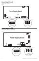
17. Output connections: Connect the devices to be powered to the removable terminals marked [– OUT1 +] to [– OUT8 +] for Maximal1RHV and Maximal3RHV. For Maximal1RV, Maximal3RV, and Maximal33RV connect devices to the second set of terminals marked [– OUT1 +] to [– OUT8 +] (Fig. 15c, pg. 12). 18. Fire Alarm Interface connection options: a. Connect the FACP trigger input to the removable terminals marked FACP1 and FACP2.
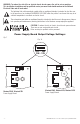
WARNING: To reduce the risk of fire or electric shock, do not expose the unit to rain or moisture. This installation should be made by qualified service personnel and should conform to the National Electrical Code and all local codes. The lightning flash with arrowhead symbol within an equilateral triangle is intended to alert the user to the presence of an insulated DANGEROUS VOLTAGE within the product’s enclosure that may be of sufficient magnitude to constitute an electric shock.
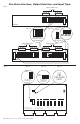
Fire Alarm Interface, Output Selection, and Input Type: Fig. 2 FIRE ALARM INTERFACE 4 3 2 4 1 3 2 INPUT TYPE Output Trigger LEDs OUTPUT SELECT 1 4 3 2 4 1 3 2 SW3 1 ON ON ON ON ON ACM8R-S 4 3 2 Fig. 2b 1 SW3 ON Fig.
Power Supply Board ON Maximal1RHV, Maximal1RV Fig. 4 Power Supply Board OFF AC DC AC FAIL LOW BAT ON 5A 250V L G NC N C NO NC C NO – BAT + – DC + NC C NO NC + C --BAT LOW BAT Fig. 4b AC FAIL Fig. 4a – BAT + NO Battery and Built-in AC Supervision Battery Charging Built-in Battery Charging Power Supply Board Maximal3RHV, Maximal3RV, Maximal33RV Fig. 5 + DC – ON + BAT – Power Supply Board AC 5A 250V L G DC N BAT BAT FAIL NC C NO NC C NO AC FAIL Fig. 5a Fig.
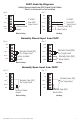
FACP Hook-Up Diagrams Polarity Reversal Input from FACP Signal Circuit Output (Polarity is referenced in alarm condition) Fig. 6 Fig. 7 GND GND IN8 FACP 1 2 RESET GND 5-30VDC -from FACP + Signal Circuit Factory Installed Jumper IN8 FACP 1 2 RESET GND Non-Latching 5-30VDC -from FACP + Signal Circuit Normally Open [NO] Reset Switch Latching Normally Closed Input from FACP Fig. 8 Fig.
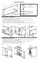
Mounting Options: Mounting Hardware Fig. 12 (Included): A Two (2) mounting brackets. B Remove center brace from rack mount chassis before proceeding with installation. Eight (8) flat head screws for mounting brackets. C Eight (8) pan head screws for faceplate. Rack Mount Installation 1. Remove center brace from rack mount chassis (Fig. 12). 2. Slide mounting brackets (A) into slots located on left and right side of rack enclosure (Fig. 13a). Use three (3) flat head screws (B) to secure brackets. 3.
Notes: MaximalRV Rack Access Power Controllers (Fused) Installation Guide - 11 -
Rack Mechanical Drawing and Dimensions 3.25” x 19.125” x 8.5” (82.6mm x 485.8mm x 215.9mm) Fig. 15 Fig. 15a Fig. 15b Fig.