
Installation Guide

Maximal3/Maximal5/Maximal7 Access Power Controllers (Fused) Installation Guide - 7 -
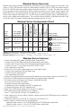
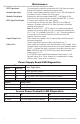
Power Supply Board Terminal Identification:
Terminal Legend Function/Description
L, G, N Connect 115VAC 60Hz to these terminals: L to hot, N to neutral.
+ DC –
Maximal3 - 12VDC @ 5A or 24VDC @ 5.4A to ACM8 boards (non power-limited)
Maximal5 - 12VDC @ 9A to ACM8 boards (non power-limited).
Maximal7 - 24VDC @ 9.4A to ACM8 boards (non power-limited).
AC FAIL
NC, C, NO
Indicates loss of AC power. To meet with UL requirements it is mandatory to connect visual
notification devices, connecting audible notification devices is optional. Relay normally
energized when AC power is present. Contact rating 1A/28VDC. AC or brownout fail is
reported within 1 minute of event.
BAT FAIL
NC, C, NO
Indicates low battery condition, e.g. connect to access control panel. Relay normally ener-
gized when DC power is present. Contact rating 1A @ 28VDC. A removed battery is reported
within 5 minutes. Battery reconnection is reported within 1 minute. Low battery threshold:
12VDC output threshold set @ approximately 10.5VDC.
24VDC output threshold set @ approximately 21VDC.
+ BAT –
Stand-by battery connections. Connect one (1) 12VDC battery to the terminals marked
[+ BAT –] for 12VDC operation
(Figs. 3 and 3a, pg. 9).
Use two (2) 12VDC batteries wired in series for 24VDC operation
(Fig. 4, pg. 10).
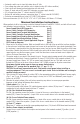
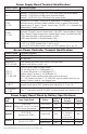
Access Power Controller Terminal Identification:
Terminal Legend Function/Description
– Power + 12VDC or 24VDC input from power supply board.
– Control + Not applicable.
TRIGGER INPUT 1-
INPUT 8 IN, GND
From normally open and/or open collector sink trigger inputs
(request to exit buttons, exit pir’s, etc.).
OUTPUT 1-
OUTPUT 8
NC, C, NO, COM
12VDC to 24VDC trigger controlled outputs:
Fail-Safe [NC positive (+) & COM Negative (–)],
Fail-Secure [NO positive (+) & COM Negative (–)],
Auxiliary output [C positive (+) & COM Negative (–)]
(When using AC power supplies polarity needs not to be observed),
NC, C, NO convert to dry form “C” 5A 24VAC/VDC rated dry outputs when fuses are
removed. Contacts shown in a non-triggered state.
FACP INTERFACE
T, + INPUT –
Fire Alarm Interface trigger input from FACP. Trigger inputs can be normally open,
normally closed from an FACP signaling circuit output
(Figs. 8-12, pg. 14).
FACP INTERFACE
NC, C, NO
Form “C” relay contact rated @ 1A/28VDC for alarm reporting (not evaluated by UL).
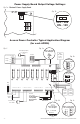
Power Supply Board Stand-by Battery Specifications:
Altronix
Model:
Power Supply Board Battery
20 Min. of
Backup
4 hr. of
Backup
24 hr. of
Backup
Maximal3
AL600ULXB
(Refer to Fig. 1a, pg. 7 for Switch
[SW1] location and position)
12VDC/40AH* N/A 5.0A N/A
24VDC/40AH* N/A 5.4A 0.7A
Maximal5
AL1012ULXB
(Factory set at 12VDC)
12VDC/12AH 9.0A
Battery capacity
for emergency
stand-by:
at least 20 min.
N/A
Maximal7
AL1024ULXB2
(Factory set at 24VDC)
24VDC/12AH 7.7A 1.2A 200mA
24VDC/65AH* N/A 7.7A 1.2A
*Note: Additional battery enclosure required (Figs. 5-7, pgs. 11-13).