
Installation Guide

Maximal3/Maximal5/Maximal7 Access Power Controllers (Fused) Installation Guide - 3 -
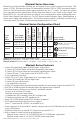
Maximal Series Overview:
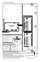
Maximal Access Power/Controllers distribute and switch power to access control systems and accessories. They
convert a 115VAC, 60Hz input into sixteen (16) independently controlled 12VDC or 24VDC fuse protected outputs.
These Fail-Safe/Fail-Secure power outputs may be converted to dry form “C” contacts. The outputs are activated
by an open collector sink or normally open (NO) dry trigger input from an Access Control System, Keypad, Push
Button, REX PIR, etc. Units will route power to a variety of access control hardware devices including: Mag Locks,
Electric Strikes, Magnetic Door Holders, etc. The FACP Interface enables Emergency Egress, Alarm Monitoring, or
may be used to trigger other auxiliary devices. The fire alarm disconnect feature is individually selectable for any
or all of the sixteen (16) outputs. All interconnecting equipment must be UL Listed.
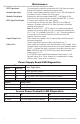
Maximal Series Configuration Chart:
Altronix
Model
Number
Power Supply
Board Output
Voltage Options
Fuse Protected
Non Power-Limited
Outputs
Maximum Current
Per ACM8 Output
115VAC 60Hz Input
Current Draw
Power Supply Board
Input
Fuse Rating
Power Supply Board
Battery
Fuse Rating
Agency Listings
and File Numbers
Maximal3
12VDC @ 5A or
24VDC @ 5.4A
16 2.5A 3.5A
5A/
250V
–
UL File # BP6714
UL 294* - UL Listed for Access
Control System Units.
General Signaling Equipment
Evaluated to CSA Standard C22.2
No.205-M1983
California State Fire
Marshal Approved
Maximal5
12VDC @ 9A 16 2.5A 2.6A
5A/
250V
15A/
32V
Maximal7
24VDC @ 9.4A 16 2.5A 4.4A
5A/
250V
15A/
32V
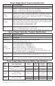
*ANSI/UL 294 7th Ed. Access Control Performance Levels:
Maximal3: Destructive Attack - I; Endurance - I; Line Security - I; Stand-by Power - IV.
Maximal5, Maximal7: Destructive Attack - I; Endurance - I; Line Security - I; Stand-by Power - I, IV.
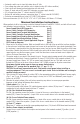
Maximal Series Features:
• Sixteen (16) independently trigger controlled outputs. Output options:
a) Sixteen (16) Fail-Safe filtered and electronically regulated power outputs.
b) Sixteen (16) Fail-Secure filtered and electronically regulated power outputs.
c) Sixteen (16) form “C” relay outputs (rated @ 5A/28VDC or VAC).
d) Any combination of the above.
• Sixteen (16) Access Control System trigger inputs. Input trigger options:
a) Sixteen (16) normally open (NO) dry trigger inputs.
b) Sixteen (16) open collector inputs.
c) Any combination of the above.
• Sixteen (16) unswitched filtered and electronically regulated aux. power outputs (outputs are rated @ 3.5A).
• Red LEDs on ACM8 board indicate individual outputs are triggered (relays energized).
• Fire Alarm disconnect (latching or non-latching) is individually selectable
for any or all of the sixteen (16) outputs.
Fire Alarm disconnect input trigger options:
a) Normally open (NO) or normally closed (NC) dry trigger input.
b) Polarity reversal input from FACP signaling circuit.
• Green LED on ACM8 board indicates FACP disconnect is triggered.
• FACP output relay indicates that FACP input is triggered
(form “C” contact rated @ 1A/28VDC, not evaluated by UL).
• Power supply input is factory installed. It provides common power for both ACM8 boards and all connected
access control devices.
• ACM8 board main fuses are rated @ 10A. Output fuses are rated @ 3.5A.
• Built-in charger for sealed lead acid or gel type batteries.
- Maximum charge current is 0.7A for AL600ULXB and AL1012ULXB power supply boards.
- Maximum charge current is 3.6A for AL1024ULXB2 power supply board.
Altronix Corp.
140 58th St. Brooklyn, NY