Maximal Series Single Power Supply Access Power Controllers (fused) Models Include: Maximal3 - 12VDC @ 5A or 24VDC @ 5.4A. - Sixteen (16) fuse protected non power-limited outputs. Maximal5 - 12VDC @ 9A. - Sixteen (16) fuse protected non power-limited outputs. Maximal7 - 24VDC @ 9.42A. - Sixteen (16) fuse protected non power-limited outputs. Installation Guide Altronix Corp. 140 58th St. Brooklyn, NY Rev. MSF052219 More than just power.TM Installing Company: _______________ Service Rep.
Table of Contents: Maximal Series Overview . . . . . . . . . . . . . . . . . . . . . . . . . . . . . . . . . . . . . . . . . . . . . . . . . . . . pg. 3 Maximal Series Configuration Chart . . . . . . . . . . . . . . . . . . . . . . . . . . . . . . . . . . . . . . . . . . . . pg. 3 Maximal Series Features. . . . . . . . . . . . . . . . . . . . . . . . . . . . . . . . . . . . . . . . . . . . . . . . . . . . . pg. 3 Maximal Installation Instructions . . . . . . . . . . . . . . . . . . . . . . . . . . . . . . .
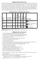
Maximal Series Overview: Maximal Access Power/Controllers distribute and switch power to access control systems and accessories. They convert a 115VAC, 60Hz input into sixteen (16) independently controlled 12VDC or 24VDC fuse protected outputs. These Fail-Safe/Fail-Secure power outputs may be converted to dry form “C” contacts. The outputs are activated by an open collector sink or normally open (NO) dry trigger input from an Access Control System, Keypad, Push Button, REX PIR, etc.
• Automatic switch over to stand-by battery when AC fails. • Zero voltage drop when unit switches over to battery backup (AC failure condition). • Short circuit and thermal overload protection with auto reset. • Green AC input and red DC output LED indicators on power supply board(s). • AC fail supervision (form “C” contact rated @ 1A/28VDC). • Battery fail and battery presence supervision (form “C” contact rated @ 1A/28VDC). • Enclosure accommodates up to four (4) 12VDC/12AH batteries.
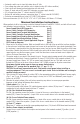
7. Input trigger options (Fig. 2, pg. 8): (a) Normally Open [NO] input trigger: Inputs 1-8 are activated by normally open or open collector sink inputs. Connect access control panel outputs, keypads, push buttons, REX PIRs, etc. to the terminals marked [IN] and [GND]. (b) Open Collector Sink inputs: Connect the access control panel open collector sink positive (+) to the terminals marked [IN] and the negative (–) to terminals marked [GND]. 8. Fire Alarm Interface options (Figs. 8-12, pgs.
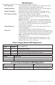
Maintenance: Unit should be tested at least once a year for the proper operation as follows: FACP Supervision: To ensure proper connection and operation of the Fire Alarm disconnect hookup please follow the appropriate procedure below: Normally Open Input: Placing a short between terminals marked [T] and [+ INP] will trigger the Fire Alarm Disconnect. Remove the short to reset. Normally Closed Input: Removing the wire from terminal marked [INP –] will trigger the Fire Alarm Disconnect.
Power Supply Board Terminal Identification: Terminal Legend L, G, N + DC – AC FAIL NC, C, NO Function/Description Connect 115VAC 60Hz to these terminals: L to hot, N to neutral. Maximal3 - 12VDC @ 5A or 24VDC @ 5.4A to ACM8 boards (non power-limited) Maximal5 - 12VDC @ 9A to ACM8 boards (non power-limited). Maximal7 - 24VDC @ 9.4A to ACM8 boards (non power-limited). Indicates loss of AC power.
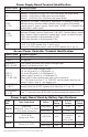
Power Supply Board Output Voltage Settings: Fig. 1a - Maximal3 Power Supply Board Fig. 1b ON SW1 ON OFF - 24V ON - 12V + DC --- OFF - 24V ON - 12V Access Power Controller Typical Application Diagram (for each ACM8): Fig. 2 Fig. 2a Intact = Dry Input Cut = Wet Input Normally Open (N.O.) Door Releasing Device FACP (Fire Alarm Control Panel) FACP Keypad Access Control Panel TRG C NO Fig.
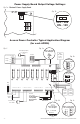
Fig. 3 - Maximal3 and Maximal5 MAIN Tamper Switch NO C NC FACP +INP- T + RETINTERFACE AC1 N NC C NO NC C NO AC FAIL BAT FAIL AC DC TRIGGER EOL SUPERVISED NO GND RESET +AUX- +INP- T + RETINTERFACE Optional Rechargeable Stand-by Battery for UL294 Applications Note: 12V batteries required Note: 12V batteries required for ULC-S319 installations. for ULC-S319 installations. CAUTION: When power supply board is set for Fig. 3b 12VDC use only one (1) 12VDC stand-by battery.
AC DC OFF - 24V ON - 12V SUPERVISED TRIGGER EOL GND RESET NO +AUX- +INP- T + RETINTERFACE BAT FAIL NO C NC FACP AC FAIL NC C NO NC C NO Tamper Switch + + Power Control AC1 Power Supply Board Neutral +INP- T + RETINTERFACE N NO C NC FACP G Optional Rechargeable Stand-by Battery MAIN MAIN Edge of Enclosure + + Power Control L Fig.
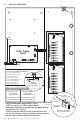
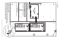
NEC Power-Limited Wiring Requirements for Maximal3: Power-limited and non power-limited circuit wiring must remain separated in the cabinet. All power-limited circuit wiring must remain at least 0.25” away from any non power-limited circuit wiring. Furthermore, all power-limited circuit wiring and non power-limited circuit wiring must enter and exit the cabinet through different conduits. One such example of this is shown below. Your specific application may require different conduit knockouts to be used.
NEC Power-Limited Wiring Requirements for Maximal5: Power-limited and non power-limited circuit wiring must remain separated in the cabinet. All power-limited circuit wiring must remain at least 0.25” away from any non power-limited circuit wiring. Furthermore, all power-limited circuit wiring and non power-limited circuit wiring must enter and exit the cabinet through different conduits. One such example of this is shown below. Your specific application may require different conduit knockouts to be used.
NEC Power-Limited Wiring Requirements for Maximal7: Power-limited and non power-limited circuit wiring must remain separated in the cabinet. All power-limited circuit wiring must remain at least 0.25” away from any non power-limited circuit wiring. Furthermore, all power-limited circuit wiring and non power-limited circuit wiring must enter and exit the cabinet through different conduits. One such example of this is shown below. Your specific application may require different conduit knockouts to be used.
FACP Hook-Up Diagrams: Fig. 8 Polarity reversal input from FACP signaling circuit output (polarity is referenced in alarm condition): CUT JUMPER FACP FACP OUTPUT EOL -- FROM FACP OUTPUT + CIRCUIT NO C NC FACP INTERFACE TRG Fig. 9 Normally Open: Non-Latching FACP trigger input: Fig. 11 Normally Open FACP Latching trigger input with reset (This output has not been evaluated by UL): FACP TRG N.O. TRIGGER INPUT N.O. TRIGGER INPUT N.C.
Notes: Maximal3/Maximal5/Maximal7 Access Power Controllers (Fused) Installation Guide - 15 -
Enclosure Dimensions (H x W x D approximate): 26” x 19” x 6.25” (660.4mm x 482.6mm x 158.8mm) 19” (482.6mm) 4” (101.6mm) 7” (177.8mm) 4” (101.6mm) 2” (50.8mm) 6.25” (158.8mm) 2” (50.8mm) 19” (482.6mm) 8.9” (226.1mm) 8.4” (213.4mm) 0.85” (21.6mm) 7” (177.8mm) 8.5” (215.9mm) 8.4” (213.4mm) 0.85” (21.6mm) 1.25” (31.75mm) 2” (50.8mm) 1” (25.4mm) 8.9” (226.1mm) 6.25” (158.8mm) 0.85” (21.6mm) 26” (660.4mm) 7” (177.8mm) 4” (101.6mm) 26” (660.4mm) 1.0” (25.4mm) 7.5” (190.