
Installation Guide

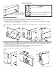

Maximal Rack Access Power Controllers (PTC) - 9 -
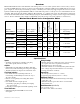
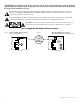
FACP Hook-Up Diagrams
Polarity Reversal Input from FACP Signal Circuit Output
(Polarity is referenced in alarm condition)
Fig. 6
GND
IN8
GND
5-30VDC
from FACP
Signal Circuit
Factory Installed
Jumper
--
+
1
2
FACP
RESET
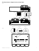
GND
IN8
GND
5-30VDC
from FACP
Signal Circuit
--
+
Normally Open [NO]
Reset Switch
1
2
FACP
RESET
Non-Latching
Normally Closed Input from FACP
Fig. 7
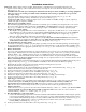
GND
IN8
GND
Factory Installed
Jumper
Normally Closed [NC] Dry
Trigger Input
1
2
FACP
RESET
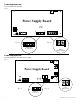
GND
IN8
GND
Normally Closed [NC] Dry
Trigger Input
Normally Open [NO]
Reset Switch
1
2
FACP
RESET
Normally Open Input from FACP
Fig. 8
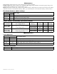
1
2
GND
FACP
IN8
RESET
GND
Normally Open [NO] Dry
Trigger Input
Factory Installed
Jumper
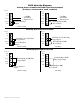
GND
IN8
GND
Normally Open [NO]
Dry Trigger Input
Normally Open [NO]
Reset Switch
1
2
FACP
RESET
Fig. 9
Fig. 10 Fig. 11
Latching
Non-Latching
Latching
Non-Latching
Latching