
Installation Guide

Maximal Rack Access Power Controllers (PTC) - 5 -
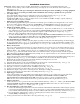
Maintenance:
Unit should be tested at least once a year for the proper operation as follows:
Output Voltage Test: Under normal load conditions the DC output voltage should be checked for proper voltage level
(Output Voltage and Stand-by Specification Charts, pg. 5).
Battery Test: Under normal load conditions check that the battery is fully charged, check specified voltage at the battery
terminalsandattheboardterminalsmarked[–BAT+]toensurethatthereisnobreakinthebatteryconnectionwires.
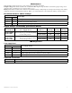
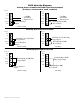
Fire Alarm Interface Switch Settings:
Switch Position
FACP Input
SW1 SW2
Open Open FACP Signal Circuit (Polarity Reversal).
Closed Closed NormallyClosed[NC]TriggerInput.
Closed Open NormallyOpen[NO]TriggerInput.
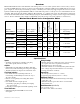
Output Voltage and Stand-by Specification Charts:
Altronix Model Power Supply Board Battery
20 Min. of
Backup
4 Hr. of
Backup
24 Hr. of
Backup
Maximal1RHD
Maximal1RD
OLS120
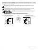
(Refer to Fig. 1a, pg. 4 for Switch [SW1]
location and position)
12VDC/40AH* N/A 3.5 amp 0.5 amp
24VDC/40AH* N/A 2.7amp 0.7amp
Maximal3RHD
Maximal3RD
Maximal33RD
AL600ULXB
(Refer to Fig. 1a, pg. 4 for Switch [SW1]
location and position)
12VDC/40AH* N/A 5.5 amp 5.5 amp
24VDC/40AH* N/A 5.5 amp 0.7amp
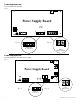
LED Diagnostics:
Power Supply Board
LED
Power Supply Status
Red (DC) Green (AC)
ON ON Normal operating condition.
ON OFF Loss of AC, Stand-by battery supplying power.
OFF ON No DC output. Short circuit or thermal overload condition.
OFF OFF No DC output. Loss of AC. Discharged battery.
Output LEDs on Front Panel
ON Output is triggered.
Blinking FACP disconnect.