
Installation Guide

- 10 - Maximal Rack Access Power Controllers (PTC)
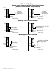
Fig. 12
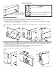
Fig. 13
Fig. 14
Mounting Options:
Rack Mount Installation
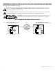
1. Remove center brace from rack mount chassis (Fig. 12, pg. 10).
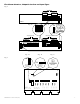
2. Slide mounting brackets (A) into slots located on left and right side of rack enclosure (Fig. 13a).
Use three (3) flat head screws (B) to secure brackets.
3. Carefully place faceplate over LEDs and secure using three (3) pan head screws (C) on top and three (3) pan head
screws (C) on the bottom of faceplate (Fig. 13b, pg. 10).
4. SlideunitintothedesiredEIA19”rackpositionandsecurewithmountingscrews(not included) (Fig. 13c, pg. 10).
B
C
A
Mounting Hardware
(Included):
Two (2) mounting brackets.
Eight (8) flat head screws for mounting brackets.
Eight (8) pan head screws for faceplate.
Wall Mount Installation
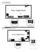
1. Carefully place faceplate over LEDs, and secure using three (3) pan head screws (C) on top and three (3) pan head
screws (C) on the bottom of faceplate (Fig. 14a).
2. Place mounting brackets (A) onto the side of the left and right side of rack enclosure (Fig. 14b).
Use three (3) flat head screws (B) to secure mounting brackets.
3- Mount rack and secure with mounting screws (not included) (Fig. 14c).
Remove center brace
from rack mount chassis
before proceeding with installation.
B
C
A
Fig. 13a Fig. 13b Fig. 13c
C
B
A
Fig. 14a Fig. 14b Fig. 14c