
Installation Guide

Maximal11F/Maximal33F/Maximal55F/Maximal77F/Maximal75F Access Power Controllers (Fused) - 8 -
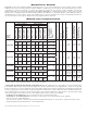
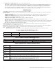
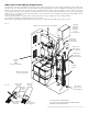
Fig. 3
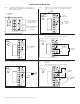
Fig. 3a
LG N
NC C NO NC C NO
BAT FAILAC FAIL
--- DC +
AC
AC1
DC
--- BAT +
+ AUX –
enable
disable
1 min.
2 hr.
AC DELAY SHUTDOWN
TRIGGER EOL
SUPERVISED
NO GND
RESET
O
N
5A 250V
Power Supply Board
LG N
NC C NO NC C NO
BAT FAILAC FAIL
--- DC +
AC
AC1
DC
--- BAT +
+ AUX –
enable
disable
1 min.
2 hr.
AC DELAY SHUTDOWN
TRIGGER EOL
SUPERVISED
NO GND
RESET
O
N
5A 250V
Power Supply Board
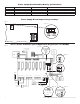
120VAC Input
60 Hz
Wire
Strap
(from
Enclosure
to Door)
Tamper Switch
Earth
Ground
Line
Neutral
Line
Neutral
+ BAT ---
CAUTION: When power supply board is set for 12VDC
use only one (1) 12VDC stand-by battery.
Connect red battery lead to
the terminal marked [+ BAT]
and to the [positive (+)]
terminal of the battery.
Connect black battery lead to
terminal marked [BAT -- ]
and to the [negative (--)]
terminal of the battery.
Optional Rechargeable
Stand-by Battery for
UL294 Applications.
Note: 12V batteries
required for
Canadian installations.
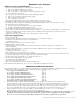
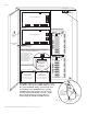
CAUTION: When power supply board is set for
12VDC use only one (1) 12VDC stand-by battery.
Keep power-limited wiring separate from non
power-limited. Use minimum 0.25" spacing.
12AH Rechargeable batteries are the largest
batteries that can fit in this enclosure. A UL
listed external battery enclosure must be
used if using the 40AH or 65AH batteries.
Optional Rechargeable
Stand-by Battery
for UL294 Applications
Note: 12V batteries required
for ULC-S319 installations.
Optional Rechargeable
Stand-by Battery
for UL294 Applications
Note: 12V batteries required
for ULC-S319 installations.
OFF --- 24V
ON --- 12V
ON
OFF --- 24V
ON --- 12V
ON
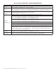
NC C NO COM
OUTPUT 1
LED1
F1
NC C NO COM
OUTPUT 2
IN GND
1
IN GND
2
IN GND
3
IN GND
4
IN GND
5
IN GND
6
IN GND
7
MAIN
IN GND
8
LED2
LED3
LED4
LED5
LED6
LED7
LED8
J2
TRG
NC C NO COM
OUTPUT 3
NC C NO COM
OUTPUT 4
NC C NO COM
OUTPUT 5
NC C NO COM
OUTPUT 6
NO C NC + INP --- T + RET -
NC C NO COM
OUTPUT 7
NC C NO COM
OUTPUT 8
--- +
Power
--- +
Control
F2
F3
F6 F7 F8
F4
F5
J1
J3
FACP INTERFACE
10A 250V
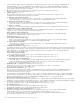
1 2 3 4
ON
1 2 3 4
ON
NC C NO COM
OUTPUT 1
LED1
F1
NC C NO COM
OUTPUT 2
IN GND
1
IN GND
2
IN GND
3
IN GND
4
IN GND
5
IN GND
6
IN GND
7
MAIN
IN GND
8
LED2
LED3
LED4
LED5
LED6
LED7
LED8
J2
TRG
NC C NO COM
OUTPUT 3
NC C NO COM
OUTPUT 4
NC C NO COM
OUTPUT 5
NC C NO COM
OUTPUT 6
NO C NC + INP --- T + RET -
NC C NO COM
OUTPUT 7
NC C NO COM
OUTPUT 8
--- +
Power
--- +
Control
F2
F3
F6 F7 F8
F4
F5
J1
J3
FACP INTERFACE
10A 250V
1 2 3 4
ON
1 2 3 4
ON
Edge of
Enclosure
to Access Control Panel
or U.L. Listed
Reporting Device
Enclosure
Sentrol
model # 3012
Tamper Switch
or equivalent
(Not Included)