
Installation Guide

- 5 - Maximal11F/Maximal33F/Maximal55F/Maximal77F/Maximal75F Access Power Controllers (Fused)
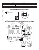
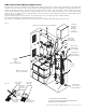
15. Multiple power supply inputs (Fig. 2, pg. 7) (Not evaluated by UL):
When using an additional Listed external power supply, jumpers J1 and J2 located on corresponding ACM8 board must be cut
(Fig. 2c, pg. 7 & Fig. 5, pg. 10). Connect external Listed power-limited access control power supply to the terminals marked
[- Control +] (These terminals are paralleled to the - Power + terminals). When using DC power supplies, polarity must be
observed. When using AC power supplies, polarity need not be observed. (Fig. 2d, pg. 7) All field wiring connections must be
made employing suitable gauge CM or FPL jacketed wire (or equivalent substitute) (Fig. 4a, pg. 7).
Maintenance:
Unit should be tested at least once a year for the proper operation as follows:
FACP Supervision: To ensure proper connection and operation of the Fire Alarm disconnect hookup. Please follow the appropriate
procedure below:
Normally Open Input: Placing a short between terminals marked [T] and [+ INP] will trigger the Fire Alarm Disconnect.
Remove the short to reset.
Normally Closed Input: Removing the wire from terminal marked [INP -- ] will trigger the Fire Alarm Disconnect.
Replace the wire to terminal marked [INP -- ] to reset.
FACP Signal Circuit Input: It is necessary to trigger the Fire Alarm System.
In all of the above scenarios the green TRG LED of the ACM8s will illuminate. All outputs selected for Fire Alarm
Disconnect will activate releasing locking devices.
Note: All outputs [OUT 1 - OUT 8] must be in a normal (de-energized) condition prior to testing. When the unit is configured for
Normally Open (Fig. 8, pg. 10) or Normally Closed (Fig. 10, pg. 10) latching operation, it is necessary to reset the Fire Alarm
Disconnect by activating the Normally Closed reset switch.
Output Voltage Test: Under normal load conditions, the DC output voltage should be checked for proper voltage level
(refer to MaximalF series Configuration Chart, pg. 2).
Battery Test: Under normal load conditions check that the battery is fully charged, check specified voltage at the battery terminals
and at the board terminals marked [+ BAT – ] to ensure that there is no break in the battery connection wires.
Note: Maximum charge current is 1.54 amp.
Expected battery life is 5 years; however, it is recommended to change batteries within 4 years or less if necessary.
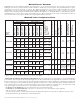
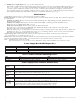
Power Supply Board LED Diagnostics:
Red (DC) Green (AC/AC1) Power Supply Status
ON ON Normal operating condition.
ON OFF Loss of AC. Stand-by battery supplying power.
OFF ON No DC output.
OFF OFF Loss of AC. Discharged or no stand-by battery. No DC output.
Access Power Controller LED Diagnostics:
LED ON OFF
LED 1- LED 8 (Red) Output relay(s) energized. Output relay(s) de-energized.
Trg (Green) FACP input triggered (alarm condition). FACP normal (non-alarm condition).
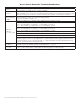
Power Supply Board Terminal Identification:
Terminal
Legend
Function/Description
L, N Connect 120VAC 60Hz to these terminals: L to hot, N to neutral. Do not use terminal marked [G].
+ DC – Factory connected to ACM8 board.
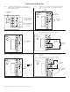
Trigger EOL
Supervised
Fire Alarm Interface trigger input from a short or FACP. Trigger inputs can be normally open, normally closed
from an FACP output circuit (power-limited input) (Fig. 3, pg. 8).
NO, GND
RESET
FACP interface latching or non-latching (power-limited) (Fig. 3, pg. 8).
+ AUX – Auxiliary Power-Limited output rated @ 1 amp (unswitched) (power-limited output) (Fig. 3, pg. 8).
AC FAIL
NC, C, NO
Indicates loss of AC power, e.g. connect to audible device or alarm panel. Relay normally energized when AC
power is present. Contact rating 1 amp @ 30VDC (power-limited) (Fig. 3, pg. 8).
BAT FAIL
NC, C, NO
Indicates low battery condition, e.g. connect to alarm panel. Relay normally energized when DC power is present.
Contact rating 1 amp @ 30VDC. A removed battery is reported within 5 minutes.
Battery reconnection is reported within 1 minute (power-limited) (Fig. 3, pg. 8).
+ BAT – Stand-by battery connections. Maximum charge current 1.54 amp (non power-limited) (Fig. 3, pg. 8).