
Installation Guide
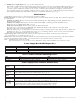
Maximal11F/Maximal33F/Maximal55F/Maximal77F/Maximal75F Access Power Controllers (Fused) - 4 -
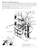
3. Select desired DC output voltage by setting SW1 to the appropriate position on the power supply board (Maximal11F
and Maximal33F) (Fig. 1, pg. 7). Maximal55F power supply is factory set at 12VDC. Maximal77F power supply is
factory set at 24VDC. Maximal75F consists of one (1) power supply board that is factory set at 12VDC, and one (1)
power supply board that is factory set at 24VDC.
4. Measure the output voltage of the unit before connecting any devices to ensure proper operation.
Improper or high voltage will damage these devices.
5. Output options (Fig. 2, pg. 7):
The unit will provide either sixteen (16) switched power outputs, sixteen (16) dry form “C” outputs, or any
combination of both switched power and form “C” outputs.
(a) Fail-Safe Switched Power outputs:
For Fail-Safe operation connect the positive (+) input of the access control devices to terminal marked [NC].
Connect the negative (-) input of the access control devices to terminal marked [COM].
(b) Fail-Secure Switched Power outputs:
For Fail-Secure operation connect the positive (+) input of the access control devices to terminal marked [NO].
Connect the negative (-) input of the access control devices to terminal marked [COM].
(c) Form “C” outputs:
When form “C” outputs are desired the corresponding output fuses (1-8) of each ACM8 board must be removed.
6. ACM8 Auxiliary Power outputs (unswitched):
Connect access control devices that require constant power to terminals marked [C] positive (+) and [COM] negative (-).
Outputs can be used to provide power for card readers, keypads etc.
eFlow Auxiliary outputs (unswitched):
For auxiliary device connection this output will not be affected by Low Power Disconnect or Fire Alarm Interface.
Connect device to terminals marked [+ AUX -- ] (Fig. 3, pg. 8).
7. Input trigger options (Fig. 2, pg. 7):
(a) Normally Open [NO] input trigger:
Inputs 1-8 are activated by normally open or open collector sink inputs. Connect access control panel outputs,
keypads, push buttons, REX PIRs, etc. to terminals marked [IN] and [GND].
(b) Open Collector Sink inputs:
Connect the access control panel open collector sink positive (+) to terminals marked [IN] and the negative (-)
to terminals marked [GND].
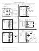
8. ACM8 Fire Alarm Interface options (Figs. 5-9, pg. 10):
A normally closed [NC] or normally open [NO] input trigger from a fire alarm control panel or a polarity reversal input from an
FACP signaling circuit will affect selected outputs. To enable FACP Disconnect for an output turn the corresponding switch(es)
[SW1-SW8] OFF on each ACM8 board. To disable FACP disconnect for an output turn the corresponding switch(es)
[SW1-SW8] ON on each ACM8 board.
(a) Normally Open [NO] input:
For non-latching hook-up refer to Fig. 6, pg. 10. For latching hook-up refer to Fig. 7, pg. 10.
(b) Normally Closed [NC] input:
For non-latching hook-up refer to Fig. 8, pg. 10. For latching hook-up refer to Fig. 9, pg. 10.
(c) FACP Signaling Circuit input trigger:
Connect the positive (+) and negative (-) from the FACP signaling circuit output to the terminals marked [+ INP -].
Connect the FACP EOL to the terminals marked [+ RET -] (polarity is referenced in an alarm condition).
Jumper located next to TRG LED must be cut (Fig. 6, pg. 10).
9. FACP Dry form “C” output (Not evaluated by UL) (Fig. 2b, pg. 7):
FACP form “C” contacts can be use to trigger reporting or signaling devices. These contacts switch
upon a fire alarm input trigger to the ACM8 boards.
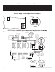
10. Stand-by Battery Connections (Figs. 3, pg. 8):
For U.S. Access Control applications batteries are optional. Batteries are required for Canadian installations (ULC-S319).
When batteries are not used, a loss of AC will result in the loss of output voltage. When the use of stand-by batteries
is desired, they must be lead acid or gel type.
Connect battery to terminals marked [-- BAT + ] (Fig. 3, pg. 8). Use two (2) 12VDC batteries connected in series for 24VDC
operation (battery leads included). Use batteries - Casil CL1270 (12V/7AH), CL12120 (12V/12AH), CL12400 (12V/40AH),
CL12650 (12V/65AH) batteries or UL recognized BAZR2 and BAZR8 batteries of an appropriate rating.
11. Battery and AC Supervision outputs (Fig. 3, pg. 8):
It is required to connect supervisory trouble reporting devices to outputs marked [AC Fail, BAT Fail] supervisory relay outputs
marked [NC, C, NO] to appropriate visual notification devices. Use 22 AWG to 18 AWG for AC Fail & Low/No Battery reporting.
12. To delay AC reporting for 2 hrs., set dip switch [AC Delay] to OFF position (Fig. 3, pg. 8).
To delay AC reporting for 1 min., set dip switch [AC Delay] to ON position (Fig. 3, pg. 8).
13. Fire Alarm Disconnect (Fig. 3, pg. 8):
To enable Fire Alarm Disconnect set dip switch [Shutdown] to ON position.
To disable Fire Alarm Disconnect set dip switch [Shutdown] to OFF position.
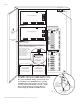
14. Installation of tamper switch (Not Included) (Fig. 3b, pg. 8):
Mount UL Listed tamper switch (Sentrol model 3012 or equivalent) at the top of the enclosure. Slide the tamper
switch bracket onto the edge of the enclosure approximately 2” from the right side (Fig. 3b, pg. 8).
Connect tamper switch wiring to the Access Control Panel input or the appropriate UL Listed reporting device.
To activate alarm signal open the door of the enclosure.