
Installation Guide

Maximal11/Maximal33/Maximal55/Maximal77/Maximal75 Access Power Controllers (Fused) - 7 -
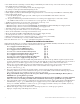
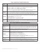
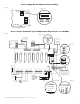
Power Supply Board Terminal Identification:
Terminal
Legend
Function/Description
L, N Connect 115VAC 60Hz to these terminals: L to hot, N to neutral.
+ DC -
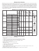
Maximal11 - 12VDC @ 3.5A or 24VDC @ 2.7A to ACM8 boards (power-limited).
Maximal33 - 12VDC @ 5.5A or 24VDC @ 5.7A to ACM8 boards (non power-limited).
Maximal55 - 12VDC @ 9.5A to ACM8 boards (power-limited).
Maximal77 - 24VDC @ 9.7A to ACM8 boards (power-limited).
Maximal75 - one (1) power supply which is 12VDC @ 9.5A to ACM8 board (non power-limited)
and one (1) power supply which is 24VDC @ 9.7A to ACM8 board (non power-limited).
AC FAIL
NC, C, NO
Indicates loss of AC power. To meet with UL requirements it is mandatory to connect visual notification
devices, connecting audible notification devices is optional. Relay normally energized when AC power is
present. Contact rating 1A @ 28VDC. AC or brownout fail is reported within 1 minute of event.
BAT FAIL
NC, C, NO
Indicates low battery condition, e.g. connect to access control panel. Relay normally energized when
DC power is present. Contact rating 1A @ 28VDC. A removed battery is reported within 5 minutes.
Battery reconnection is reported within 1 minute.
Low battery threshold:
12VDC output threshold set @ approximately 10.5VDC.
24VDC output threshold set @ approximately 21VDC.
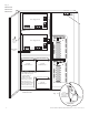
+ BAT -
Stand-by battery connections. Connect one (1) 12VDC battery to the terminals marked [+ BAT -]
for 12VDC operation (Fig. 3, pg. 10, Fig. 5, pg. 12). Use two (2) 12VDC batteries wired in series for
24VDC operation (Figs. 3-5, pgs. 10-12).
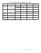
Access Power Controller Terminal Identification:
Terminal Legend Function/Description
- Power + 12VDC or 24VDC input from power supply board.
- Control +
(only applicable for
Maximal11)
These terminals can be connected to an external UL Listed power-limited access control
power supply to provide isolated operating power for the ACM8 (jumpers J1 and J2 must be
removed). All field wiring connections must be made employing suitable gauge CM or FPL
jacketed wire (or equivalent substitute), (Figs. 6a-9a, pgs. 13-16).
TRIGGER
INPUT 1-INPUT 8
IN, GND
From normally open and/or open collector sink trigger inputs
(request to exit buttons, exit pir’s, etc.)
OUTPUT 1-
OUTPUT 8
NC, C, NO, COM
12VDC to 24VDC trigger controlled outputs:
Fail-Safe [NC positive (+) & COM Negative (-)],
Fail-Secure [NO positive (+) & COM Negative (-)],
Auxiliary output [C positive (+) & COM Negative (-)]
(When using AC power supplies polarity need not be observed),
NC, C, NO convert to dry form “C” 5A 24VAC/VDC rated dry outputs when fuses
are removed. Contacts shown in a non-triggered state.
FACP INTERFACE
T, + INPUT --
Fire Alarm Interface trigger input from FACP. Trigger inputs can be normally open,
normally closed from an FACP signaling circuit output (Figs. 10-15, pg. 17).
FACP INTERFACE
NC, C, NO
Form “C” relay contact rated @ 1A/28VDC for alarm reporting (not evaluated by UL).