
Installation Guide


MaxiFit3FE/MaxFit5FE/MaxFit7FE Expandable Power Systems - 5 -
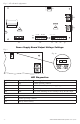
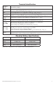
Terminal Identification:
Terminal
Legend
Function/Description
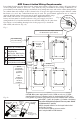
L, N
Connect 120VAC 60Hz to these terminals: L to hot, N to neutral.
Do not use terminal marked [G] (Fig. 1a, pg. 4).
+ DC – Refer to MaxFitFE Series Configuration Chart, pg. 2 (Fig. 1h, pg. 4).
Trigger EOL
Supervised
Fire Alarm Interface trigger input from a short or FACP. Trigger inputs can be normally open,
normally closed from an FACP output circuit (power-limited input) (Fig. 1d, pg. 4).
NO, GND
RESET
FACP interface latching or non-latching (power-limited) (Fig. 1e, pg. 4).
+ AUX – Auxiliary Power-Limited output rated @ 1A (unswitched) (Fig. 1f, pg. 4).
AC FAIL
NC, C, NO
Indicates loss of AC power, e.g. connect to audible device or alarm panel.
Relay normally energized when AC power is present.
Contact rating 1A @ 30VDC (power-limited) (Fig. 1b, pg. 4).
BAT FAIL
NC, C, NO
Indicates low battery condition, e.g. connect to alarm panel. Relay normally energized
when DC power is present. Contact rating 1A @ 30VDC.
A removed battery is reported within 5 minutes.
Battery reconnection is reported within 1 minute (power-limited) (Fig. 1b, pg. 4).
+ BAT –
Stand-by battery connections.
Maximum charge current 1.54A (non power-limited) (Fig. 1g, pg. 4).
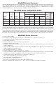
Stand-by Battery Specifications:
Battery MaxFit3FE MaxFit5FE and MaxFit7FE
7AH 10 Mins./6A 5 Mins./10A
12AH 30 Mins./6A* 30 Mins./10A*
40AH Over 4 Hours/6A* Over 2 Hours/10A*
65AH Over 4 Hours/6A* Over 4 Hours/10A*
*Only these configurations can be utilized in ULC-S319 installations.