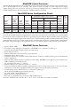
Expandable Power Systems Installation Guide Models Include: MaxFit3FE - 12VDC/24VDC @ 6A. MaxFit5FE - 12VDC @ 10A. MaxFit7FE - 24VDC @ 10A. Rev. MFEPS080119 More than just power.TM Installing Company: _________________ Service Rep.
MaxFitFE Series Overview: Altronix MaxFit Expandable Power Systems provide system designers and installers with optimum power choices and the highest levels of versatility. They provide 12VDC or 24VDC via single output power supply/ charger. Includes AC fail, low battery, and battery presence monitoring. Enclosure accommodates up to four (4) 12VDC/12AH batteries. All interconnecting equipment must be UL Listed.
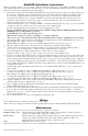
MaxFitFE Installation Instructions: Wiring methods shall be in accordance with the National Electrical Code/NFPA 70/NFPA 72/ANSI, The Canadian Electrical Code, Part 1 and with all local codes and authorities having jurisdiction. The product must be located indoors within the protected premises. 1. Mount unit in desired location. Mark and predrill holes in the wall to line up with the top three keyholes in the enclosure. Install three upper fasteners and screws in the wall with the screw heads protruding.
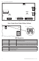
OFF --- 24V ON --- 12V ON Fig. 1 - eFlow Board configuration --- DC + 1h --- BAT + 1i 1g 10A 10A 32V 5A 250V 5A 250V AC1 L G N AC FAIL BAT FAIL AC DELAY SHUTDOWN O N NC C NO 1a NC C NO AC DC 1b 1 min. 2 hr. enable disable 1c TRIGGER EOL SUPERVISED NO GND RESET 1d 1e + AUX – 1f Power Supply Board Output Voltage Settings: OFF - 24V ON - 12V Fig. 2a ON ON Fig.
Terminal Identification: Terminal Legend Function/Description L, N Connect 120VAC 60Hz to these terminals: L to hot, N to neutral. Do not use terminal marked [G] (Fig. 1a, pg. 4). + DC – Refer to MaxFitFE Series Configuration Chart, pg. 2 (Fig. 1h, pg. 4). Trigger EOL Supervised Fire Alarm Interface trigger input from a short or FACP. Trigger inputs can be normally open, normally closed from an FACP output circuit (power-limited input) (Fig. 1d, pg. 4).
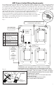
NEC Power-Limited Wiring Requirements: Power-limited and non power-limited circuit wiring must remain separated in the cabinet. All power-limited circuit wiring must remain at least 0.25” away from any non power-limited circuit wiring. Furthermore, all power-limited circuit wiring and non power-limited circuit wiring must enter and exit the cabinet through different conduits. One such example of this is shown below. Your specific application may require different conduit knockouts to be used.
Notes: -7- MaxiFit3FE/MaxFit5FE/MaxFit7FE Expandable Power Systems
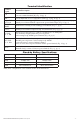
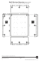
MaxFit Enclosure Dimensions (approximate): 20.5” x 16.5” x 6.25” (520.7mm x 419.1mm x 158.8mm) 1.25” 7.00” 7.00” 1.25” 1.25” 6.25 1.25” 16.50” 0.75” 1.25” 1.25” 1.00” 1.50” 1.50” 0.569” 8.75” 8.75” 20.50” 8.75” 8.75” 1.50” 1.50” 1.25” 1.25” 1.25” 1.25” 7.00” 7.00” 1.25” Altronix is not responsible for any typographical errors. 140 58th Street, Brooklyn, New York 11220 USA | phone: 718-567-8181 | fax: 718-567-9056 website: www.altronix.com | e-mail: info@altronix.