MaxFit FE Series Expandable Power Systems Models Include: MaxFit3FE - 12VDC/24VDC @ 6A. MaxFit5FE - 12VDC @ 10A. MaxFit7FE - 24VDC @ 10A. Installation Guide Rev. MFEPS080119 More than just power.TM Installing Company: _______________ Service Rep.
MaxFitFE Series Overview: Altronix MaxFit Expandable Power Systems provide system designers and installers with optimum power choices and the highest levels of versatility. They provide 12VDC or 24VDC via single output power supply/ charger. Includes AC fail, low battery, and battery presence monitoring. Enclosure accommodates up to four (4) 12VDC/12AH batteries. All interconnecting equipment must be UL Listed.
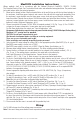
MaxFitFE Installation Instructions: Wiring methods shall be in accordance with the National Electrical Code/NFPA 70/NFPA 72/ANSI, The Canadian Electrical Code, Part 1 and with all local codes and authorities having jurisdiction. The product must be located indoors within the protected premises. 1. Mount unit in desired location. Mark and predrill holes in the wall to line up with the top three keyholes in the enclosure. Install three upper fasteners and screws in the wall with the screw heads protruding.
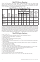
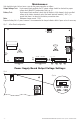
Maintenance: Unit should be tested at least once a year for the proper operation as follows: Output Voltage Test: Under normal load conditions the DC output voltage should be checked for proper voltage level (MaxFitFE Configuration Chart, pg. 2). Battery Test: Under normal load conditions check that the battery is fully charged, check specified voltage at the battery terminals and at the board terminals marked [– BAT +] to ensure that there is no break in the battery connection wires.
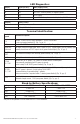
LED Diagnostics: Red (DC) ON ON OFF OFF Green (AC/AC1) ON OFF ON OFF Power Supply Status Normal operating condition. Loss of AC. Stand-by battery is supplying power. No DC output. Loss of AC. Discharged or no stand-by battery. No DC output. Red (Bat) ON OFF Battery Status Normal operating condition. Battery fail/low battery. Terminal Identification: Terminal Legend Function/Description L, N Connect 120VAC 60Hz to these terminals: L to hot, N to neutral. Do not use terminal marked [G] (Fig. 1a, pg.
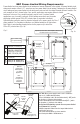
NEC Power-Limited Wiring Requirements: Power-limited and non power-limited circuit wiring must remain separated in the cabinet. All power-limited circuit wiring must remain at least 0.25” away from any non power-limited circuit wiring. Furthermore, all power-limited circuit wiring and non power-limited circuit wiring must enter and exit the cabinet through different conduits. One such example of this is shown below. Your specific application may require different conduit knockouts to be used.
Notes: -7- MaxiFit3FE/MaxFit5FE/MaxFit7FE Expandable Power Systems Installation Guide
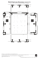
MaxFit Enclosure Dimensions (approximate): 20.5” x 16.5” x 6.25” (520.7mm x 419.1mm x 158.8mm) 1.25” (31.8mm) 7.00” (177.8mm) 7.00” (177.8mm) 1.25” (31.8mm) 1.25” (31.8mm) 6.25” (158.8mm) 1.25” (31.8mm) 16.50” (419.1mm) 0.75” (19.1mm) 1.50” (38.1mm) 1.25” (31.8mm) 1.00” (25.4mm) 1.25” (31.8mm) 1.50” (38.1mm) 8.75” (222.3mm) 8.75” (222.3mm) 20.50” (520.7mm) 8.75” (222.3mm) 8.75” (222.3mm) 0.569” (14.5mm) 1.50” (38.1mm) 1.50” (38.1mm) 1.25” (31.8mm) 1.25” (31.8mm) 1.25” (31.8mm) 1.25” (31.