
Installation Instructions

Overview:
LPS3C24X linear power supply/charger is specifically designed to provide the power needed by the most demanding
security and access control applications. It converts a 115VAC 50/60Hz input to a 2.5 amp 24VDC continuous output.
Specifications:
Input:
• Input115VAC50/60Hz,0.7amp.
Output:
• 24VDCoutput.
• 2.5ampcontinuoussupplycurrent.
• Filteredandelectronicallyregulatedoutput.
• Thermalandshortcircuitprotectionwithautoreset.
Battery Backup:
• Automaticswitchovertostand-bybatterywhenACFails.
• Built-inchargerforsealedleadacidorgeltypebatteries.
• Maximumchargecurrent0.5amp.
• Fusedbatteryprotection(circuitbreakersavailable).
• Includesbatteryleads.
Visual Indicators:
• ACinputandDCoutputLEDindicators.
Enclosure Dimensions (H x W x D):
15.5”x12”x4.5”(393.7mmx304.8mmx114.3mm)
Power Supply Voltage Output Specifications:
Output VDC Maximum Load DC
24VDC 2.5 amp
Installation Instructions:
WiringmethodsshouldbeinaccordancewiththeNationalElectricalCode/NFPA70/NFPA72/ANSI,andwithalllocal
codes and authorities having jurisdiction. Product is intended for indoor use only.
1. Mountunitinthedesiredlocation.Markandpredrillholesinthewalltolineupwiththetoptwokeyholesinthe
enclosure. Install two upper fasteners and screws in the wall with the screw heads protruding. Place the enclosure’s
upperkeyholesoverthetwoupperscrews;levelandsecure.Markthepositionofthelowertwoholes.Removethe
enclosure.Drillthelowerholesandinstallthreefasteners.Placetheenclosure’supperkeyholesoverthetwo
upperscrews.Installthetwolowerscrewsandmakesuretotightenallscrews(Enclosure Dimensions, pg. 2).
Secure enclosure to earth ground.
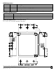
2. ConnectACpowertotheblackandwhiteflyingleadsofthetransformer(Fig. 1).
Use18AWGorlargerforallpowerconnections(Battery,DCoutput).
3. Measureoutputvoltagebeforeconnectingdevices.Thishelpsavoidingpotentialdamage.
Keep power-limited wiring separate from non power-limited wiring (115VAC / 60Hz Input, Battery Wires).
Minimum 0.25” spacing must be provided.
CAUTION: Do not touch exposed metal parts. Shut branch circuit power before installing or servicing equipment.
There are no user serviceable parts inside. Refer installation and servicing to qualified service personnel.
4. Connectdevicestobepoweredtotheterminalsmarked[–DC+](Fig. 1).
5. Connectbatterytotheterminalsmarked[–BAT+](Fig.1)ontheunit(batteryleadsincluded).
Note:Whenbatteriesarenotused,alossofACwillresultinlossofoutputvoltage.
Maintenance:
Unit should be tested at least once a year for the proper operation as follows:
Output Voltage Test:UndernormalloadconditionstheDCoutputvoltageshouldbecheckedforthepropervoltagelevel
(seepowersupplyvoltageoutputspecificationschart).
Battery Test:Undernormalloadconditionscheckthatthebatteryisfullycharged,checkspecifiedvoltagebothatthebat-
teryterminalandattheboardterminalsmarked[-BAT+]toensurethatthereisnobreakinthebatteryconnectionwires.
Note:Maximumchargingcurrentunderdischargeis500mA.
Note:Expectedbatterylifeis5years;however,itisrecommendedchangingbatteriesin4yearsorlessifneeded.
LPS3C24X
Linear Power Supply/Charger
XFMR
White
Lead
Black
Lead
AC
DC
AC
AC
-- DC +
-- BAT +
SW1
12V-CLOSED
24V-OPEN
Input 115VAC
50/60Hz
.7 amp
Fig. 1