
Installation Guide

- 4 - LINQ8ACM(CB)
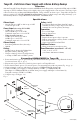
6. Output Options (program output options via LINQ software):
LINQ8ACM(CB) will provide up to eight (8) switched power outputs plus eight (8) unswitched auxiliary
power outputs.
Switched Power outputs:
Connect the negative (–) input of the device being powered to the terminal marked [COM].
• For Fail-Safe operation connect the positive (+) input of the device being powered to the terminal
marked [NC].
• For Fail-Secure operation connect the positive (+) input of the device being powered to the terminal
marked [NO].
Auxiliary Power Outputs (unswitched):
Connect positive (+) input of the device being powered to the terminal marked [C] and the negative (–)
of the device being powered to the terminal marked [COM]. Output can be used to provide power for
card readers, keypads etc.
7. Turn main power on after all devices are connected.
8. Input Trigger Options (program trigger input options via LINQ software):
Note: If Fire Alarm disconnect is not used, connect a 10 kOhm resistor to terminals marked [GND and EOL].
Input:
Connect dry access control (NC/NO) input to terminals marked [+ INP1 –] to [+ INP8 –].
Open Collector Sink Input:
Connect the open collector sink input to the terminal marked [+ INP1 –] to [+ INP8 –].
Wet (Voltage) Input Configuration:
Carefully observing polarity, connect the voltage input trigger wires and the supplied 10K resistor to
terminals marked [+ INP1 –] to [+ INP8 –].
9. Fire Alarm Interface Options (program fire alarm interface options via LINQ software):
A normally closed [NC], normally open [NO] input or polarity reversal input from FACP signaling circuit
will trigger selected outputs.
Normally Open Input:
Wire your FACP relay and 10K resistor in parallel on terminals marked [GND] and [EOL].
Normally Closed Input:
Wire your FACP relay and 10K resistor in series on terminals marked [GND] and [EOL].
10. FACP Dry NC output:
Connect desired device to be triggered by the unit’s dry contact output to the terminals marked [NC] and [C].
When [EOL JMP] is in the DIS position, the output is of 0 Ohm resistance in a normal condition.
When [EOL JMP] is in the EN position, a 10k resistance will be passed to next device when in a
normal condition.
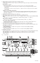
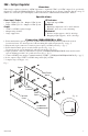
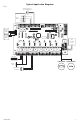
Fig. 2 - LINQ8ACM
COM -
+PWR2 +PWR1
+ PWR1 - + PWR2 -
COM -
F- R- GND GND C
F+ R+ EOL RST NC FACP
+ PS1 - + BAT - + PS2 - + BAT -
BAT 1 FUSE BAT 2 FUSE
NO C NC COM NO C NC COM NO C NC COM NO C NC COM NO C NC COM NO C NC COM NO C NC COM NO C NC COM
+PWR2
+PWR1
EN<-->DIS
PWR2<-->PWR1
PWR2<-->PWR1
PWR2<-->PWR1
PWR2<-->PWR1
PWR2<-->PWR1
PWR2<-->PWR1
PWR2<-->PWR1
PWR2<-->PWR1
OUT1
OUT7
OUT2
OUT3
OUT4
OUT5
OUT6
OUT8
NC C NO
BAT AC
Tamper
NC C NO
+ INP1 -+ INP2 -+ INP3 -+ INP4 -
+ INP5 -+ INP6 -+ INP7 -+ INP8 -
AC
BAT
FACP
Beat
Out1
Out2
Out3
Out4
Out5
Out6
Out7
Out8
OFF
PWR2
PWR1
A
Y
B
F
E
X
E
G
H
J
I
K
L
M
N
O
C
U
T
D
P
Y
QRS
W
V
Z