
Installation Guide

LINQ8ACM(CB) - 3 -
• Eight (8) programmable trigger inputs:
- Normally open (NO).
- Normally colsed (NC).
- Open collector sink inputs.
- Wet Input (5VDC - 24VDC) with 10k resistor.
- Any combination of the above.
• Programmable port IDs.
• Monitor power supply(ies) input for voltage and currect limits (high/low).
• Input and output current calibration.
• Programmable timer events.
• Programmable user levels.
• Enable or disable alerts by type.
• Programmable alert reporting delay/
Fire Alarm Disconnect:
• Fire Alarm disconnect (Inactive, latching or non-latching) is individually selectable for any or all of
the eight (8) outputs.
Fire Alarm disconnect input options:
a) Supervised Normally Open [NO] or Normally Closed [NC] dry contact input.
b) Polarity reversal input from FACP signaling circuit.
• FACP input WET is rated 5-30VDC 7mA.
• FACP dry input EOL requires 10K end of line resistor.
• FACP output relay [NC]: Either Dry 1A/28VDC, 0.6 Power Factor or 10K resistance with [EOL JMP] intact.
Fuse Ratings:
• Main input fuses rated 15A/32V each.
• LINQ8ACM: Output fuses are rated 3A/32V.
• LINQ8ACMCB: Output PTCs are rated 2A.
LED Indicators:
• Green AC LED: indicates AC trouble condition.
• Green BAT LED: indicates battery trouble condition.
• Green FACP LED: indicates FACP disconnect is triggered.
• Flashing Blue Heartbeat LED: indicates network connection.
• Individual OUT1 - OUT8 Red LEDs: indicate outputs are triggered.
• Individual Voltage LEDs: indicate 12VDC (Green) or 24VDC (Red).
Environmental:
• Operating temperature: 0ºC to 49ºC ambient.
• Humidity: 20 to 93%, non-condensing.
Mechanical:
• Board Dimensions (W x L x H approximate): 8” x 4.5” x 1.25” (203.2mm x 114.3mm x 31.8mm).
• Product weight (approx.): 0.7 lb. (0.32 kg).
• Shipping weight (approx.): 0.95 lb. (0.43 kg).
Installation Instructions:
Wiring methods shall be in accordance with the National Electrical Code NFPA 70/NFPA 72/ ANSI / Canadian
Electrical Code / CAN/ULC-S524/ULC-S527/ULC-S537, and with all local codes and authorities having
jurisdiction. Product is intended for indoor dry use only.
Refer to Sub-Assembly Installation Instruction for mounting Rev. MS020119.
Carefully review:
Terminal/Connector Identification (pg. 5) Typical Application Diagram (pg. 9)
LED Diagnostics (pg. 6) Hook-up Diagrams (pg. 15-16)
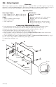
1. Mount LINQ8ACM(CB) in the desired location/enclosure. When mounting LINQ8ACM(CB) alone,
use female/female spacers (provided). When mounting with optional VR6 voltage regulator or Tango1B PoE
Driven Power Supply, use female/female spacers (provided) between LINQ8ACM(CB) and VR6 or Tango1B
(Fig. 3, pg. 7, Fig. 4, pg. 8).
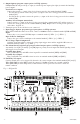
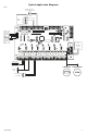
2. Ensure all output jumpers [OUT1] - [OUT8] are placed in the OFF (center) position.
3. Connect low voltage DC power supplies to terminals marked [+ PWR1 –], [+ PWR2 –].
Note: For VR6 and Tango1B installation please refer to pg. 7, 8.
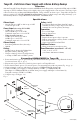
4. Set each output [OUT1] - [OUT8] to route power from Power Supply 1 or 2 (Fig. 1).
Note: Measure output voltage before connecting devices.
This helps avoiding potential damage.
5. Turn main power off before connecting devices.
OFF
PWR2
PWR1
Fig. 1