Please be sure to visit altronix.com for latest firmware and installation instructions Dual Input Network Access Power Controllers Installation and Programming Manual Models include: LINQ8ACM - Network Access Power Controller - Eight (8) Fused Outputs LINQ8ACMCB - Network Access Power Controller - Eight (8) PTC Outputs DOC#: LINQ8ACM Rev. 100219 More than just power.
Overview: Altronix LINQ8ACM(CB) are dual input network access power controllers which can be installed in Altronix wall and rack mount enclosures to facilitate access control deployment. Access Power Controller’s dual input design allows power to be steered from one (1) or two (2) independent low voltage 12 or 24 VDC Altronix power supplies to eight (8) independently controlled fuse (LINQ8ACM) or PTC (LINQ8ACMCB) protected outputs.
• Eight (8) programmable trigger inputs: - Normally open (NO). - Normally colsed (NC). - Open collector sink inputs. - Wet Input (5VDC - 24VDC) with 10k resistor. - Any combination of the above. • Programmable port IDs. • Monitor power supply(ies) input for voltage and currect limits (high/low). • Input and output current calibration. • Programmable timer events. • Programmable user levels. • Enable or disable alerts by type.
6. Output Options (program output options via LINQ software): LINQ8ACM(CB) will provide up to eight (8) switched power outputs plus eight (8) unswitched auxiliary power outputs. Switched Power outputs: Connect the negative (–) input of the device being powered to the terminal marked [COM]. • For Fail-Safe operation connect the positive (+) input of the device being powered to the terminal marked [NC].
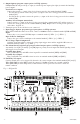
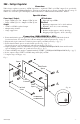
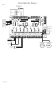
Terminal/Connector Identification: A B C D E F G H I J K L M N O P Q R S T U V W X Terminal/Legend Description A B C D +E F GFirst H DC I Jpower K L M N O P Q R S T U V W X Y Z – PWR1 supply input. A B C D E + F G H Second I J DC K power L M supply N O input. P Q R S T U V W X Y Z – PWR2 Q R 12VDC B C DOutput E FLED G H I Individual J K L output M N voltage O P LEDs. S T U(Green) V W or X 24VDC Y Z (Red). C D E F G H I J Individual K L Moutput N O voltage P Q selection R S T jumper.
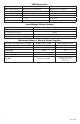
LED Diagnostics: LED LED 1- LED 8 (Red) FACP Green Output 1-8 Red Output 1-8 AC BAT ON Output relay(s) de-energized. FACP input triggered (alarm condition). 12VDC 24VDC AC Fail Battery Fail OFF Output relay(s) energized. FACP normal (non-alarm condition). – – AC Normal Battery Normal Input/Output Voltage Ratings: Input Voltage and Source 5VDC (from VR6 regulator) 12V (from VR6 regulator) 12VDC (from external power supply) 24VDC (from external power supply) Output Voltage Rating 5VDC 12VDC 11.7-12VDC 23.
VR6 - Voltage Regulator Overview: VR6 voltage regulator converts a 24VDC input into a regulated 5VDC or 12VDC output. It is specifically designed to work with LINQ8ACM(CB) by allowing to mount the Access Power Controller directly on top of VR6 to save enclosure space and simplify connections. Refer to VR6 Installation Guide Rev. 050517. Specifications: Power Input / Output: • Input: 24VDC @ 1.75A – Output: 5VDC @ 6A. • Input: 24VDC @ 3.5A – Output: 12VDC @ 6A.
Tango1B - PoE Driven Power Supply with Lithium Battery Backup Overview: Altronix Tango1B Voltage Regulator converts an IEEE802.3bt PoE input into a regulated 24VDC and/or 12VDC output up to 65W. It eliminates the need for a high voltage power supply inside of an enclosure. The Tango 8-pin connector allows for stacking with LINQ8ACM(CB), saving valuable enclosure space.
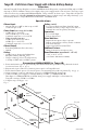
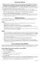
Typical Application Diagram: Fig. 5 Normally Open (N.O.
Network Setup: –––––––––––––––––––––––––––––––––––––––––––––––––––––––––––––––––––––––––––––––––––––––––– Please be sure to visit altronix.com for latest firmware and installation instructions. –––––––––––––––––––––––––––––––––––––––––––––––––––––––––––––––––––––––––––––––––––––––––– Network Programming Via Altronix Dashboard USB Connection: The USB connection on the LINQ8ACM(CB) is used to setup the network parameters.
Click the button labeled Submit Network Settings. A dialog box will display “New network settings will take effect after the server is rebooted”. Click OK. To access the LINQ8ACM(CB) via the Altronix Dashboard refer to the Dashboard Installation and Programming Manual located on supplied flash drive. b.
Battery Backup: select whether the output will be backed up in the event of a power failure. Uncheck the associated box to disable battery back for that output. 9. Over/Under Current: Enter both the High and Low current limits for the associated output. If either of these limits are exceeded an alert message and/or email notification will be generated. 10. Over/Under Voltage: Enter both the High and Low voltage limits for the associated output.
Static: a. b. c. d. e. f. g. IP Address: Enter the IP address assigned to the LINQ8ACM(CB) by the network administrator. Subnet Mask: Enter the Subnet of the network. Gateway: Enter the TCP/IP gateway of the network access point (router) being used. Gateway configuration is required to properly receive emails from the device. HTTP Port: Enter the HTTP port number assigned to LINQ8ACM(CB) module by the network administrator to allow remote access and monitoring. The default inbound port setting is 80.
F. Network Security Settings: 1. Click on the Security tab to access the Security Settings screen. 2. Click the appropriate tab at the top of the screen for the fields to be programmed. Policies: Select the security warning to be displayed when logging in to the system by checking to display and unchecking not to display the warning message. Self-Signed Certificate Setup: Generating a self-signed SSL Certificate and Key: 1. State: Two letter code representing the state where the organization is located.
Hook-Up Diagrams: FACP R- GND GND C R+ EOL RST NC Jumper FCOM - COM - F- F+ Jumper F+ R- GND GND C R+ EOL RST NC FACP Fig. 6 - Daisy-chaining one or more LINQ8ACM(CB) units. EOL Jumper [EOL JMP] should be installed in the EOL position. Non-Latching. FACP R- GND GND C R+ EOL RST NC FCOM - COM - F- F+ N.O. Switch F+ R- GND GND C R+ EOL RST NC FACP Fig. 7 - Daisy-chaining one or more LINQ8ACM(CB) units. EOL Jumper [EOL JMP] should be installed in the EOL position. Latching Single Reset.
Hook-Up Diagrams: Polarity reversal input from FACP signaling circuit output (polarity is referenced in alarm conditiion). Non-Latching. Polarity reversal input from FACP signaling circuit output (polarity is referenced in alarm condition). Latching. Fig. 10 - FACP R- GND GND C R+ EOL RST NC Jumper F- -- COM - COM - -- Fig. 12 - Normally Closed trigger input (Latching). R- GND GND C R+ EOL RST NC Jumper 10K EOL FCOM - FCOM - Fig. 14 - Normally Open trigger input (Latching).