Video • Data Active UTP Transceiver Hub Installation Guide Models Include: HubWayLDH8 HubWayLDH16 - UL Listed eight (8) Camera Channels - UL Listed sixteen (16) Camera Channels Rev. 032108 More than just power.
Overview: Altronix HubWayLDH8/16 Active UTP Transceiver Hub transmits UTP video and RS422/RS485 data over a single CAT-5 or higher structured cable. Unit provides 8 or 16 camera channels in a space saving 1U EIA 19” rack mount chassis which may be rack, wall or shelf mounted. Video transmission range is up to 3000 ft. max. per channel. Units are compatible with fixed or PTZ cameras.
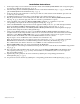
Installation Instructions: 1. Set the input voltage selector switch located on the left side of the HubWayLDH8/LDH16 unit (facing front panel) for 115VAC or 230VAC operation (Fig. 1i, pg. 4). 2. Attach mounting brackets to HubWayLDH unit for rack or wall mount installation (Figs. 5-6, pg. 8). Affix rubber pads to HubWayLDH for shelf installation (Fig. 7, pg. 8). 3.
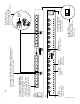
-4- PICTURE GAIN 16 1 14 2 3 13 4 12 11 GAIN PICTURE DATA 1-8 6 10 7 9 GAIN 8 CH 5-8 1f - Gain: Regulates the output video and sync levels. GAIN PICTURE GAIN PICTURE 5 1e - Picture: Adjusts video quality. PICTURE GAIN PICTURE GAIN PICTURE GAIN PICTURE 15 1d - BNC Connector: Video outputs to head end equipment (DVR).
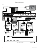
Typical Applications: Fig. 2 Head End Equipment (DVR) RS485 Monitor Video Data Rear 8 7 PICTURE GAIN 1 2 3 4 CH 1-4 5 6 7 8 6 5 4 3 PICTURE GAIN PICTURE GAIN PICTURE GAIN PICTURE GAIN PICTURE 2 1 GAIN PICTURE GAIN PICTURE AC POWER GAIN CH 5-8 DATA 1-8 Front CAT-5 Max. video 3000 ft.
Typical Applications: Fig. 3 Head End Equipment (DVR) RS485 Monitor Video Data Rear 8 7 PICTURE GAIN 1 2 3 4 CH 1-4 5 6 7 8 6 5 4 3 PICTURE GAIN PICTURE GAIN PICTURE GAIN PICTURE GAIN PICTURE 2 1 GAIN PICTURE GAIN PICTURE GAIN AC POWER CH 5-8 DATA 1-8 Front CAT-5 CAT-5 Video Power Max. video 3000 ft.
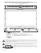
1U EIA 19” Rack Mount Chassis Mechanical Drawing & Dimensions (H x W x D): 1.625” x 19.125” x 8.5” (42mm x 486mm x 216mm) REAR 1.625" 16 PICTURE GAIN 15 14 13 12 PICTURE GAIN PICTURE GAIN PICTURE GAIN PICTURE 11 GAIN PICTURE 10 9 GAIN PICTURE GAIN PICTURE 8 GAIN PICTURE GAIN 4 3 PICTURE GAIN PICTURE GAIN PICTURE GAIN PICTURE 7 6 5 GAIN PICTURE 2 1 GAIN PICTURE GAIN PICTURE GAIN AC POWER TOP & BOTTOM 17.625" 8.
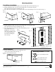
Mounting Options: Rack Mount Installation 1- Remove and discard factory installed screws from both sides of rack chassis (Fig. 5a). 2- Install mounting brackets (A) on the left and right side of rack chassis using the four (4) flat head screws (B) (included) (Fig. 5b). 3- Place unit into desired EIA 19” rack position and secure with mounting screws (not included) (Fig. 5c). Fig. 5 Fig. 5a Fig. 5b Fig.