
Installation Instructions User Manual

HubW
a
yEX16/HubW
a
yEX32
Active Hub Unit
-
7
-
1.625"
8
.5"
.75"
19.125"
17.625"
(ON)
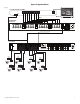
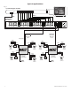
1 2 3 4 5 6 7 8 9 10 11 12 13 14 15 16
A
CTIVE ACTIVE
17 18 19 20 21 22 23 24 25 26 27 28 29 30 31 32
16 15 14 13 12 11 10 9
32 31 30 29 28 27 26 25
8 7 6 5 4 3 2 1
24 23 22 21 20 19 18 17
C
H 13 - 16
C
H 29 - 32 CH 25 - 28
C
H 9 - 12 CH 5 - 8
C
H 21 - 24 CH 17 - 20
D
ATA
C
H 1 - 4
A
C POWER
EX
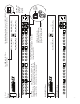
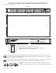
1U EIA 19” Rack Mount Chassis Mechanical Drawing & Dimensions:
1.625”H x 19.125”W x 8.5”D
TOP & BOTTOM
REAR
FRONT
Fig. 6
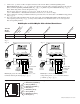
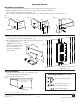
Illuminated master power disconnect circuit breaker:
• OFF position Circuit breaker tripped – Switch not illuminated.
• RESET (ON) position – Switch illuminated.
The lightning flash with arrow head symbol within an equilateral triangle is intended to alert the user to the
presence of an insulated “DANGEROUS VOLTAGE” within the products enclosure that may be of sufficient
magnitude to constitute an electric shock.
The e
xclamation point within an equilateral triangle is intended to aler
t the user to the presence of impor
tant
operating and maintenance (servicing) instructions in the literature accompanying the appliance.
CAUTION: To reduce the risk of electric shock do not open enclosure. There
are no user serviceable parts inside. Refer servicing to qualified service personnel.