Video • Data • Power Active UTP Transceiver Hub with Integral Isolated Camera Power Installation Guide HubWayEX16SP - UL Listed sixteen (16) Channel Active UTP Transceiver Hub with Integral Isolated Camera Power Rev. 011810 More than just power.
Overview: Altronix HubWayEX16SP Active UTP Transceiver Hub w/Integral Isolated Camera Power employs automatic gain control (AGC) to transmit UTP video, RS422/RS485 data and power over a single CAT-5 or higher structured cable. Units provide 16 camera channels in a space saving 1U EIA 19” rack mount chassis which may be rack, wall or shelf mounted. Video transmission range is up to one (1) mile max. per channel.
10. 11. 12. 13. 14. 15. 16. 17. 18. HubWayEX16SP (Fig. 1a, pg. 4). Plug the RJ45 connector at the opposite end of the structured cable into the RJ45 jack of the Video Balun/Combiner located at camera 1. • For 24VAC cameras use Altronix model HubWayAv Video Balun/Combiner (Fig. 3a, pg. 5). • For 12VDC cameras use Altronix model HubWayDv Video Balun/Combiner (Figs. 3b, pg. 5). Repeat steps 6-9 for each additional camera (Channels 2-16 for HubWayEX16SP).
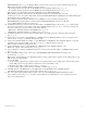
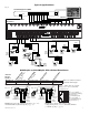
-4- 16 15 1 14 2 OFF RESET 1 2 1f - BNC Connector: Video outputs to head end equipment (DVR). Rear OFF RESET 3 3 13 4 4 + DATA -1-8 CH 1-4 12 + DATA -1-8 CH 1-4 5 11 5 6 6 10 7 7 9 8 8 28VAC OFF 24VAC CH 5-8 28VAC OFF 24VAC CH 5-8 1c - LED(s) 1-16: Power indicators. 8 8 6 10 11 5 12 7 6 5 1g - LED(s) 1-16: Video signal indicators.
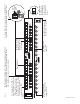
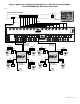
Typical Applications: Fig. 2 Head End Equipment (DVR) RS485 Monitor Video Data Rear Panel 16 15 14 13 12 11 10 9 8 7 6 5 4 3 2 1 AC POWER 1 2 3 4 CH 1-4 5 6 7 8 CH 5-8 9 10 11 12 28VAC OFF 24VAC + DATA 1-8 CH 9-12 13 14 15 16 CH 13-16 28VAC OFF 24VAC + DATA 9-16 Front Panel CAT-5 Video CAT-5 Video Power Video Power Video Power Data Power Video Power HubWayDv Max. video 5000 ft.
Typical Application Utilizing HubSat4D/Di as a Remote Accessory Module with HubWayEX16SP UTP Transceiver Hub: Fig.
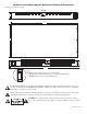
1U EIA 19” Rack Mount Chassis Mechanical Drawing & Dimensions: 1.625”H x 19.125”W x 8.5”D REAR 1.625" 16 15 14 13 12 11 10 9 8 7 6 5 4 3 2 1 AC POWER TOP & BOTTOM 17.625" 8.5" FRONT 1 2 3 4 CH 1-4 + DATA -1-8 5 6 7 8 CH 5-8 9 28VAC OFF 24VAC 10 11 12 CH 9-12 13 14 15 + DATA -9-16 16 CH 13-16 28VAC OFF 24VAC 19.125" .75" (ON) Fig. 6 Illuminated master power disconnect circuit breaker: • OFF position Circuit breaker tripped – Switch not illuminated.
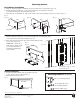
Mounting Options: Rack Mount Installation 1- Remove and discard factory installed screws from both sides of rack chassis (Fig. 7a). 2- Install mounting brackets (A) on the left and right side of rack chassis using the four (4) flat head screws (B) (included) (Fig. 7b). 3- Place unit into desired EIA 19” rack position and secure with mounting screws (not included) (Fig. 7c). Fig. 7 Fig. 7b Fig. 7a Fig.