
Installation Instructions


HubSat8Di - 3 -
7. Plug the RJ45 connector at one end of the CAT-5 or higher structured cable into the RJ45 jack marked [PVD1]
on Circuit Board A (Fig.1i,pg.5). Plug the RJ45 connector at the opposite end of the CAT-5 or higher structured
cable into the RJ45 jack of the Video Balun/Combiner to be installed at camera 1.
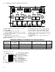
• For24VACcamerasuseAltronixmodelHubWayAv/HubWayAv2 Video Balun/Combiner (Figs.2a,2b,2e,pg.6).
• For12VDCcamerasuseAltronixmodelHubWayDvVideoBalun/Combiner(Figs.2c,2d,pg.6).
The total cable distance must not exceed 750 ft. for video transmission between the HubSat8D and each camera.
Repeat this step for all other camera channels [PVD2-4] on Circuit Board A and [PVD1-4] on Circuit Board B.
8. SetilluminatedmasterpowerdisconnectcircuitbreakertotheRESET(ON)position(Fig.3a,pg.6).Power
LEDs(Green)oftheHubSat8DiwillilluminatewhenACpowerispresent(Fig.1e,pg.5)and HubWayAv or
HubWayDvVideoBalun/CombinerLEDswillilluminate,indicatingpowerispresent(Fig.2b,2d,pg.6).
9. Measure the output voltage at each Video Balun/Combiner (Figs.2b,2d,pg.6) before making connections to
each camera to ensure proper operation and avoid possible damage.
10. Set illuminated master power disconnect circuit breaker to the (OFF) position (Fig.3a,pg.6).
11. Connect power outputs of HubWayAv, HubWayAv2 or HubWayDv Video Balun/Combiners to power inputs
of cameras (Figs.2a-2e,pg.6).Polarity must be observed.
• HubWayAv/HubWayAv2-Terminalsmarked[ACPOWER](Figs.2a,2b,2e,pg.6).
• HubWayDv-Terminalsmarked[–12VDC+](Figs.2c,2d,pg.6).
12. Connect the terminals marked [+ DATA -- ] of HubWayAv, HubWayAv2 or HubWayDv Video Balun/Combiners to
the data input terminals of cameras for PTZ control (Figs.2b-2d,pg.6). Polarity must be observed.
When using fixed cameras disregard this step.
13. Connect the BNC connector of HubWayAv, HubWayAv2 or HubWayDv Video Balun/Combiners to the BNC video
outputs of the cameras (Figs.2b-2d,pg.6).
14. SetilluminatedmasterpowerdisconnectcircuitbreakertotheRESET[ON]position(Fig.3a,pg.6).
15. ThepowerLEDs(Green)oftheHubSat8DiwillilluminatewhenACpowerispresent(Fig.1e,pg.5).
Note:IfanyofthepowerLEDsarenotilluminatedthecausemaybeduetothefollowing:
a. AC mains fail.
b. Illuminated master power disconnect circuit breaker is tripped.
c. An individual power output voltage switch is set to the OFF position (Fig.1d,pg.5).
d. A PTC is tripped due to a short circuit or overload condition for one or more channels/power outputs.
ToresetthePTC:
1. Set the voltage output selector switch for that corresponding channel to the OFF position. Switch must
remain in the OFF position for approximately 2 minutes in order for the PTC to reset (Fig.1d,pg.5).
2. Eliminatethetroublecondition(shortcircuitoroverload).
3. Set the voltage output selector switch for either 24VAC or 28VAC (Fig.1d,pg.5).
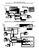
HubSat8Di for use as a Remote Accessory Module with HubWay/HubWayLD/HubWayLDH UTP Transceiver Hubs.
After completing steps 1-4 of Installation Instructions for HubSat8Di Passive UTP Transceiver Hub with Integral Camera
Power proceed with the following.
1. For fixed cameras, run two (2) CAT-5 cables between HubSat8Di and HubWay, HubWayLD or HubWayLDH to allow
video transmission of up to eight (8) cameras. For PTZs, run three (3) CAT-5 cables between HubSat8Di and
HubWay, HubWayLD or HubWayLDH (Fig.5,pg.7).
a. Connect one (1) of the CAT-5 cables to the RJ45 jack marked [Video 1-4] on Circuit Board A. Connect the
opposite end of this CAT-5 cable into the RJ45 jack marked [CH 1-4] of HubWay, HubWayLD or
HubWayLDH unit (Fig.5,pg.7).
b. Connect the second CAT-5 cable to the RJ45 jack marked [Video 1-4] on Circuit Board B. Connect the
opposite end of this CAT-5 cable into the RJ45 jack marked [CH 5-8] of HubWay, HubWayLD or
HubWayLDH unit (Fig.5,pg.7).
c. For data (PTZ) connect the third CAT-5 cable to the RJ45 jack marked [Data 1-4] on Circuit Board A. Connect
the opposite end of this CAT-5 cable into any unused RJ45 jack marked [1-16] of HubWay, HubWayLD or
HubWayLDH unit (Fig.5,pg.7).
Note: Data inputs of HubWay, HubWayLD or HubWayLDH units must be wired in parallel for proper operation.
When using fixed cameras disregard this step.
2. Plug the RJ45 connector at one end of the CAT-5 or higher structured cable into the RJ45 jack marked [PVD1]
on Circuit Board A (Fig.1i,pg.5). Plug the RJ45 connector at the opposite end of the CAT-5 or higher structured
cable into the RJ45 jack of the Video Balun/Combiner to be installed at camera 1.
• For24VACcamerasuseAltronixmodelHubWayAv/HubWayAv2 Video Balun/Combiner (Figs.2a,2b,2e,pg.6).
• For12VDCcamerasuseAltronixmodelHubWayDvVideoBalun/Combiner(Figs.2c,2d,pg.6).