
Installation Instructions User Manual

- 4 -
HubSat4WP
The total cable distance must not exceed 750 ft. for video transmission between the HubSat4WP and each camera.
R
epeat this step for all other camera channels [PVD2-4].
3
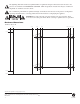
. Set illuminated master power disconnect circuit breaker to the RESET (ON) position
(
Fig. 4a, pg. 6)
p
ower LEDs
(
Green) of the HubSat4WP will illuminate when AC power is present
(
Fig. 1e, pg. 4)
a
nd HubWayAv, HubWayDv
or HubWayDvi Video Balun/Combiner LEDs will illuminate indicating power is present
(Fig. 2b, 2d, pg. 6).
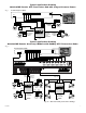
4. Measure the output voltage at each Video Balun/Combiner (Figs. 2b, 2d, pg. 6) before making connections to
each camera to insure proper operation and avoid possible damage.
5. Set illuminated master power disconnect circuit breaker to the (OFF) position
(Fig. 4a, pg. 6).
6. Connect power outputs of HubWayAv, HubWayDv or HubWayDvi Video Balun/Combiners to power inputs
of cameras
(Figs. 2a-2d, pg. 6). Polarity must be observed.
• HubWayAv - Terminals marked [AC POWER]
(Figs. 2a, 2b, pg. 6).
• HubWayDv/HubWayDvi - Terminals marked [– 12VDC +]
(Figs. 2c, 2d, pg. 6).
7. Connect the terminals marked [+ DATA --] of HubWayAv, HubWayDv or HubWayDvi Video Balun/Combiners
to data input terminals of cameras for PTZ control
(Figs. 2b-2d, pg. 6). Polarity must be observed.
When using fixed cameras disregard this step.
8. Connect the BNC connector of HubWayAv, HubWayDv or HubWayDvi Video Balun/Combiners to the
BNC video outputs of cameras
(Figs. 2b-2d, pg. 6).
9. Set illuminated master power disconnect circuit breaker to the RESET (ON) position
(Fig. 4a, pg. 6).
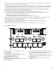
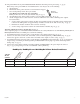
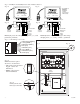
Fig. 1 -
HubSat Circuit Board
PVD1
VIDEO1 VIDEO2 VIDEO3 VIDEO4
PVD2 PVD3 PVD4
+ DATA -
DATA 1-4 VIDEO 1-4
2
8VAC
2
4VAC
2
8VAC
2
4VAC
2
8VAC
2
4VAC
2
8VAC
2
4VAC
OFF
OFF
OFF
OFF
AUX1 AUX2 AUX3 AUX4
1a - BNC Connector: Video in from remote camera
video out to DVR.
1b - Output PTCs: Protects each output.
1c - Power Terminals: 24VAC/28VAC power outputs.
1d - Output
V
oltag
e Switches:
Selects
24VAC/28VAC/OFF for each output.
1e - LED(s) 1-4: P
ower output indicators.
1f - Data: RS422/RS485 input from head end equipment
(DVR) for PTZ control.
1g - Channels 1-4: Single CAT-5 or higher structured
cable out to HubWay, HubWayLD or HubWayLDH enables
transmission of up to four (4) video signals.
1h - Data: CAT-5 or higher structured cable to data port
on HubW
a
y
, HubW
a
yLD or HubW
a
yLDH or head end
equipment (DVR).
1i - Channels 1-4: CA
T
-5 or higher str
uctured cab
le
to cameras.
1a
1i
1b
1c
1d
1e
1f
1g1h
1c