
Installation Instructions User guide

HubSat4Di - 5 -
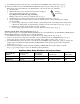
HubWay Video Balun/Combiner Reference Chart:
Altronix Model
Number
Output Voltage
to camera
Input Voltage
from HubSat Camera Type Power LED
HubWayAv
*24VAC/28VAC *24VAC/28VAC
Use with AC cameras
Green
HubWayDv
12VDC *24VAC/28VAC
Use with AC cameras
Red
*Based on camera load and structured cable length.
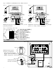
9. SetilluminatedmasterpowerdisconnectcircuitbreakertotheRESET(ON)position(Fig.4a,pg.6).
10. ThepowerLEDs(Green)oftheHubSat4DiwillilluminatewhenACpowerispresent(Fig.1e,pg.4).
Note:IfanyofthepowerLEDsarenotilluminatedthecausemaybeduetothefollowing:
a. AC mains fail.
b. Illuminated master power disconnect circuit breaker is tripped.
c. Oneorbothprimaryin-linefuse(s)areblown.
Note: Replace fuse with same type and rating:
Primaryin-linefusesarerated@3.5A/250V(Fig.4b,pg.6).
d. AnindividualpoweroutputvoltageswitchissettotheOFFposition(Fig.1d,pg.4).
e. A PTC is tripped due to a short circuit or overload condition for one or more channels/power outputs.
ToresetthePTC:
1. SetthevoltageoutputselectorswitchforthatcorrespondingchanneltotheOFFposition.Switchmust
remainintheOFFpositionforapproximately2minutesinorderforthePTCtoreset(Fig.1d,pg.4).
2. Eliminatethetroublecondition(shortcircuitoroverload).
3. Setthevoltageoutputselectorswitchforeither24VACor28VAC(Fig.1d,pg.4).
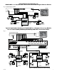
Alternate 24VAC fixed camera hookup (Fig. 6a, pg. 7).
After completing steps 1-5 of Installation Instructions Remote Accessory Module for use with HubWay, HubWayLD or
HubWayLDH UTP Transceiver Hubs proceed with the following.
1. Setilluminatedmasterpowerdisconnectcircuitbreakertothe(OFF)position(Fig.4a,pg.6).
2. Connect one end of the coaxial cable to the BNC connector marked [Video1] on HubSat4Di (Fig.1a,pg.4).
Connect the opposite end of the coaxial cable to the BNC video output of camera 1 (Fig.6a,pg.7).
3. SetilluminatedmasterpowerdisconnectcircuitbreakertotheRESET(ON)position(Fig.4a,pg.6)measure the
output voltage at terminal pair marked [AUX1] on HubSat4Di to insure proper operation and avoid possible
damage (Fig.1c,pg.4).
4. Connect the power output terminal pair marked [AUX1] on HubSat4Di to the power inputs of camera 1
(Fig.1c,pg.4).Repeatsteps1-3foreachadditionalcamera[AUX2-4].
Primary
In-lineFuse