
Installation Instructions User guide

HubSat4Di - 3 -
The total cable distance must not exceed 750 ft. for video transmission between the HubSat4Di and each camera.
Repeat this step for all other camera channels [PVD2-4].
8. SetilluminatedmasterpowerdisconnectcircuitbreakertotheRESET(ON)position(Fig.4a,pg.6)power
LEDs(Green)oftheHubSatwillilluminatewhenACpowerispresent(Fig.1e,pg.4)and HubWayAv, HubWayDv
or HubWayDvi Video Balun/Combiner LEDs will illuminate indicating power is present (Fig.2b,2d,pg.6).
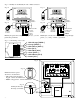
9. Measure the output voltage at each Video Balun/Combiner (Figs.2b,2d,pg.6) before making connections to
each camera to insure proper operation and avoid possible damage.
10. Setilluminatedmasterpowerdisconnectcircuitbreakertothe(OFF)position(Fig.4a,pg.6).
11. Connect power outputs of HubWayAv, HubWayDv or HubWayDvi Video Balun/Combiners to power inputs
of cameras (Figs.2a-2d,pg.6).Polarity must be observed.
• HubWayAv-Terminalsmarked[ACPOWER](Figs.2a,2b,pg.6).
• HubWayDv/HubWayDvi-Terminalsmarked[–12VDC+](Figs.2c,2d,pg.6).
12. Connect the terminals marked [+ DATA -- ] of HubWayAv, HubWayDv or HubWayDvi Video Balun/Combiners
to data input terminals of cameras for PTZ control (Figs.2b-2d,pg.6). Polarity must be observed.
When using fixed cameras disregard this step.
13. Connect the BNC connector of HubWayAv, HubWayDv or HubWayDvi Video Balun/Combiners to the
BNC video outputs of cameras (Figs.2b-2d,pg.6).
14. SetilluminatedmasterpowerdisconnectcircuitbreakertotheRESET(ON)position(Fig.4a,pg.6).
15. ThepowerLEDs(Green)oftheHubSat4DiwillilluminatewhenACpowerispresent(Fig.1e,pg.4).
Note:IfanyofthepowerLEDsarenotilluminatedthecausemaybeduetothefollowing:
a. AC mains fail.
b. Illuminated master power disconnect circuit breaker is tripped.
c. Primary in-line fuse is blown.
Note: Replace fuse with same type and rating:
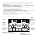
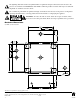
Primaryin-linefuseisrated@3.5A/250V(Fig.4b,pg.6).
d. AnindividualpoweroutputvoltageswitchissettotheOFFposition(Fig.1d,pg.4).
e. A PTC is tripped due to a short circuit or overload condition for one or more channels/power outputs.
ToresetthePTC:
1. SetthevoltageoutputselectorswitchforthatcorrespondingchanneltotheOFFposition.Switchmust
remainintheOFFpositionforapproximately2minutesinorderforthePTCtoreset(Fig.1d,pg.4).
2. Eliminatethetroublecondition(shortcircuitoroverload).
3. Setthevoltageoutputselectorswitchforeither24VACor28VAC(Fig.1d,pg.4).
HubSat4Di for use as a Remote Accessory Module with HubWay/HubWayLD/HubWayLDH UTP Transceiver Hubs.
After completing steps 1-4 of Installation Instructions HubSat4Di Passive UTP Transceiver Hub with Integral Isolated
Camera Power proceed with the following.
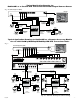
1. ForfixedcamerasrunasingleCAT-5cablebetweenHubSat4DiandHubWay,HubWayLDorHubWayLDHto
allowvideotransmissionofuptofour(4)cameras.ForPTZsruntwo(2)CAT-5cablesbetweenHubSat4Diand
HubWay, HubWayLD or HubWayLDH (Fig.6,pg.7).
a. Connectone(1)oftheCAT-5cablestotheRJ45jackmarked[Video1-4]onHubSat4Di. Connect the
opposite end of this CAT-5 cable into the RJ45 jack marked [CH 1-4] of HubWay, HubWayLD or
HubWayLDH unit (Fig.6,pg.7).
b. Fordata(PTZ)connectthesecondCAT-5cabletotheRJ45jackmarked[Data1-4]onHubSat4Di. Connect
the opposite end of this CAT-5 cable into any unused RJ45 jack marked [1-16] of HubWay, HubWayLD or
HubWayLDH unit (Fig.6,pg.7).
Note: Data inputs of HubWay, HubWayLD or HubWayLDH units must be wired in parallel for proper operation.
When using fixed cameras disregard this step.
2. Plug the RJ45 connector at one end of the CAT-5 or higher structured cable into the RJ45 jack marked [PVD1]
on HubSat4Di (Fig.1i,pg.4). Plug the RJ45 connector at the opposite end of the CAT-5 or higher structured
cable into the RJ45 jack of the Video Balun/Combiner to be installed at camera 1.
• For24VACcamerasuseAltronixmodelHubWayAvVideoBalun/Combiner(Figs.2a,2b,pg.6).
• For12VDCcamerasuseAltronixmodelHubWayDvVideoBalun/Combiner(Figs.2c,2d,pg.6).
• Fornon-isolated12VDCcamerasuseAltronixmodelHubWayDviVideoBalun/Combiner(Figs.2c,2d,pg.6).
The total cable distance must not exceed 750 ft. for video transmission between the HubSat4Di and each camera.
Repeat this step for all other camera channels [PVD2-4].
Primary
In-lineFuse