
Installation Instructions


eFlow102NV Series Installation Guide - 9 -
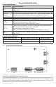
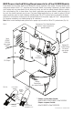
NC C NO NC
C NO
AC FAIL BAT FAIL
TRIGGER
AC DCAC1
EOLNOGND
SUPERVISED RESET
+AUX-
- BAT +- DC +
L G N
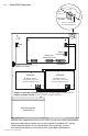
Battery & AC
Supervision Circuit
power-limited
Battery
Connection
P N
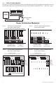
PD8/PD8CB
P N
PD8/PD8CB
DC Output to Devices*
(refer to Fig. 3a, 3b, 4a, 4b
for board configuration, pg. 6)
DC Output to Devices*
(refer to Fig. 3a, 3b, 4a, 4b
for board configuration, pg. 6)
220VAC power mains
Ground
Lug
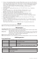
CAUTION: Power supply board is factory set for 12VDC. Use only one (1) 12VDC stand-by battery.
Keep power-limited wiring separate from non power-limited. Use minimum 0.25" spacing.
12AH Rechargeable batteries are the largest batteries that can fit in this enclosure.
A
UL listed external battery enclosure must be used if using 40AH or 65AH batteries.
Optional Rechargeable
Stand-by Battery
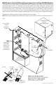
Fig. 7 - eFlow102NXV Configuration
Tamper Switch
(included)
To Access Control Panel or
UL Listed Reporting Device
Edge of
Enclosure
Enclosure
* Outputs are non power-limited: eFlow102NXV, eFlow102NX8V, eFlow102NX16V.
Outputs are power-limited: eFlow102NX8DV, eFlow102NX16DV.