
Installation Instructions


- 6 - eFlow102NV Series Installation Guide
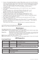
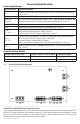
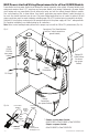
Fig. 2 - Battery Trouble Indication
Wire one leg of a power-limited power source to the indicating lamp. Wire the second leg of the power source to
the indicating lamp in series with the battery fail relay contact terminals marked [BAT FAIL - C, NO] (Fig. 2, pg. 6).
NC C NO NC C NO
BAT FAILAC FAIL
POWER
SOURCE
RED INDICATING
LAMP
––––––––––––––––––––––––––––––––––––––––––––––––––––––––––––––––––––––––––––––––––––––––––
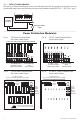
Power Distribution Module(s):
Fig. 3a - PD8 Power Distribution Board Fig. 3b - PD8CB - Power Distribution Board
Non Power-Limited Outputs Power-Limited Outputs
Fig. 4a - PD16W Power Distribution Board Fig. 4b - PD16WCB - Power Distribution Board
Non Power-Limited Outputs Power-Limited Outputs
N
COMMON POWER OUTPUTS
P
FUSED POWER OUTPUTS
1 2 3 4 5 6 7 8
D1
INPUT
R1
LED
DC Output to devices
1P-8P Power Outputs,
1N-8N Common Outputs
From Power Supply
Board
(Factory Installed)
Replace fuses with the same type and rating 3.5A/250V
N
COMMON POWER OUTPUTS
P
FUSED POWER OUTPUTS
1 2 3 4 5 6 7 8
D1
INPUT
R1
LED
DC Output to devices
1P-8P Power Outputs,
1N-8N Common Outputs
From Power Supply
Board
(Factory Installed)
common
outputs
protected
outputs
P
N
NPS
Input
12345678
9 10 11 12 13 14 15 16
P
N
3.5A 250V
For continuous protection against risk of fire
replace fuses with same type and rating
DC Output to devices
1P-16P Power Outputs, 1N-16N Common Outputs
From
Power
Supply
Board
(Factory
Installed)
NPS
Input
NP
common
outputs
protected
outputs
P
N
12345678
9 10 11 12 13 14 15 16
DC Output to devices
1P-16P Power Outputs, 1N-16N Common Outputs
From
Power
Supply
Board
(Factory
Installed)