
Installation Instructions


eFlow102NV Series Installation Guide - 5 -
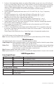
Terminal Identification:
Power Supply/Charger
Terminal Legend Function/Description
L, N
Connect 220VAC 50/60Hz to these terminals: L to hot, N to neutral (non power-limited)
(Fig. 1a, pg. 5).
– DC + 12VDC nominal @ 10A continuous output (power-limited output) (Fig. 1h, pg. 5).
Trigger EOL
Supervised
Fire Alarm Interface trigger input from a short or FACP. Trigger inputs can be normally open,
normally closed from an FACP output circuit (power-limited input) (Fig. 1d, pg. 5).
NO, GND RESET FACP interface latching or non-latching (power-limited) (Fig. 1e, pg. 5).
+ AUX – Auxiliary power-limited output rated @ 1A (unswitched) (Fig. 1f, pg. 5).
AC Fail
NC, C, NO
Indicates loss of AC power, e.g. connect to audible device or alarm panel.
Relay normally energized when AC power is present.
Contact rating 1A @ 30VDC (power-limited) (Fig. 1b, pg. 5).
Bat Fail
NC, C, NO
Indicates low battery condition, e.g. connect to alarm panel. Relay normally energized
when DC power is present. Contact rating 1A @ 30VDC.
A removed battery is reported within 5 minutes.
Battery reconnection is reported within 1 minute (power-limited) (Fig. 1b, pg. 5).
– BAT +
Stand-by battery connections. Maximum charge current 1.54A (non power-limited)
(Fig. 1g, pg. 5).
Power Distribution Module
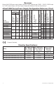
Terminal Legend PD8/PD8CB Terminal Legend PD16W/PD16WCB Function/Description
1P to 8P 1P to 16P Positive DC power outputs.
1N to 8N 1N to 16N Negative DC power outputs.
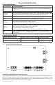
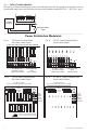
Fig. 1 - eFlow102NV Board Configuration
1a 1b
1
g
1
h
1e 1f1d1c
NC C NO NC C NO
AC FAIL BAT FAIL
TRIGGER EOL
SUPERVISED
AC DCAC1
NO GND
RESET
+ AUX -
--- BAT +
L G N
1 min enable
2 hr disable
--- DC +
––––––––––––––––––––––––––––––––––––––––––––––––––––––––––––––––––––––––––––––––––––––––––
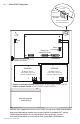
Trouble/Time Limited Warning of Stand-by Batteries:
The Time Limited Warning circuit must be connected for local or remote annunciation with an Amber or Red LED to
indicate DC Trouble (low battery, loss of battery or when 95% of the stand-by battery has been depleted). Connect
the circuit to the Batt Fail relay contacts to an appropriate input of a Burglar Alarm or Access Control Panel. The
following figure shows the circuitry needed for local annunciation.