
Installation Instructions


- 4 - eFlow102NV Series Installation Guide
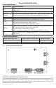
5. For Access Control applications batteries are optional. When batteries are not used, a loss of AC will result
in the loss of output voltage. When the use of stand-by batteries is desired, they must be lead acid or gel type.
Connect battery to terminals marked [– BAT + ] (Fig. 1g, pg. 5). Use two (2) 12VDC batteries connected in
series for 24VDC operation (battery leads included). Use batteries - Casil CL1270 (12V/7AH), CL12120
(12V/12AH), CL12400 (12V/40AH), CL12650 (12V/65AH) batteries or BAZR2 batteries of
an appropriate rating.
6. Connect appropriate signaling notification devices to AC FAIL & BAT FAIL (Fig. 1b, pg. 5) supervisory
relay outputs.
7. To delay AC reporting for 2 hrs. set DIP switch [AC Delay] to OFF position (Fig. 1c, pg. 5).
To delay AC reporting for 1 min. set DIP switch [AC Delay] to ON position (Fig. 1c, pg. 5).
Note: Must be set to ON position for Burglar Alarm Applications.
8. To enable Fire Alarm Disconnect set DIP switch [Shutdown] to ON position (Fig. 1c, pg. 5).
To disable Fire Alarm Disconnect set DIP switch [Shutdown] to OFF position (Fig. 1c, pg. 5).
9. Trigger terminals are end of a line resistor supervised (10k ohms). Opening or shorting trigger terminals
will cause [DC] output to shutdown (Fig. 1d, pg. 5).
10. Place a jumper for non-latching FACP. A momentary short on these terminals resets FACP latching
[Trigger EOL Shutdown] (Fig. 1e, pg. 5).
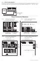
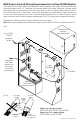
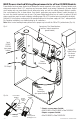
11. For Access Control Applications: mount tamper switch (Altronix model TS112 or equivalent) at the top of
the enclosure. Slide tamper switch bracket onto the edge or the enclosure approx. 2” from the right side
(Fig. 5, pg. 7 or Fig. 7, pg. 9).
Connect tamper switch wiring to the Access Control Panel input or the appropriate reporting device.
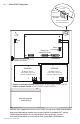
Wiring:
Use 18 AWG or larger for all low voltage power connections.
Note: Take care to keep power-limited circuits separate from non power-limited wiring (220VAC, Battery).
Maintenance:
Unit should be tested at least once a year for the proper operation as follows:
Output Voltage Test: Under normal load conditions, the DC output voltage should be checked for proper voltage
level eFlow102NV: 12VDC nominal rated @ 10A max.
Battery Test: Under normal load conditions check that the battery is fully charged, check specified voltage
(12VDC @ 13.2) both at battery terminal and at the board terminals marked [– BAT +] to
ensure that there is no break in the battery connection wires.
Note: Maximum charging current under discharges is 1.54A.
Note: Expected battery life is 5 years, however it is recommended changing batteries in 4 years or less if needed.
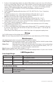
LED Diagnostics:
Power Supply/Charger
Red (DC) Green (AC/AC1) Power Supply Status
ON ON Normal operating condition.
ON OFF Loss of AC. Stand-by battery supplying power.
OFF ON No DC output.
OFF OFF Loss of AC. Discharged or no stand-by battery. No DC output.
Power Distribution Module
Green (AC) Power Distribution Module Status
ON Normal operating condition.
OFF No Power Output.