
Installation Instructions


eFlow102NV Series Installation Guide - 3 -
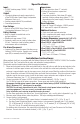
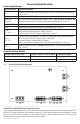
Specifications:
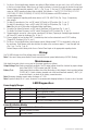
Installation Instructions:
Wiring methods shall be in accordance with the National Electrical Code/NFPA 70/NFPA 72/ANSI, The Canadian
Electrical Code, Part 1 and with all local codes and authorities having jurisdiction.
The product must be located indoors within the protected premises.
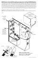
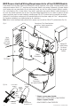
1. Mount unit in desired location. Mark and predrill holes in the wall to line up with the top two keyholes in the
enclosure. Install two upper fasteners and screws in the wall with the screw heads protruding. Place the
enclosure’s upper keyholes over the two upper screws, level and secure. Mark the position of the lower two
holes. Remove the enclosure. Drill the lower holes and install the two fasteners. Place the enclosure’s upper
keyholes over the two upper screws. Install the two lower screws and make sure to tighten all screws
(Enclosure Dimensions, pgs. 11-12). Secure enclosure to earth ground.
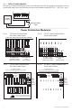
2. Connect unswitched AC power (220VAC 50/60Hz) to terminals marked [L, N] (Fig. 1a, pg. 5).
Use 14 AWG or larger for all power connections. Secure green wire lead to earth ground lug.
Keep power-limited wiring separate from non power-limited wiring (220VAC 50/60Hz Input, Battery
Wires). Minimum 0.25” spacing must be provided.
CAUTION: Do not touch exposed metal parts. Shut branch circuit power before installing or
servicing equipment. There are no user serviceable parts inside.
Refer installation and servicing to qualified service personnel.
For Fire Alarm applications the outputs are “Special Applications” only, see list (refer to Appendix A, pg. 12).
3. Measure output voltage before connecting devices. This helps avoiding potential damage.
4. Connect devices to be powered:
a. For eFlow102NV/eFlow102NXV connect devices to terminals marked [– DC +] (Fig. 1h, pg. 5).
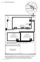
b. For other Power Distribution Models connect devices to be powered to terminal pairs 1 to 8 marked
[1P & 1N] through [8P & 8N] (Fig. 3a & 3b, pg. 6) or 1 to 16 marked [1P & 1N] through [16P & 16N]
(Fig. 4a & 4b, pg. 6) carefully observing correct polarity.
For auxiliary device connection: this output will not be affected by Low Power Disconnect or Fire Alarm
Interface. Connect device to terminals marked [+ AUX –] (Fig. 1f, pg. 5).
Input:
• 220VAC (working range 198VAC - 256VAC),
50/60Hz.
Output:
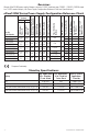
• For output voltage and supply current refer to
eFlow102NV series Power Supply Configuration
Reference Chart, pg. 2.
• Auxiliary output rated @ 1A (unswitched).
• Overvoltage protection.
Fuse Ratings:
• Refer to eFlow102NV Series Power Supply
Configuration Reference Chart, pg. 2.
Battery Backup:
• Built-in charger for sealed lead acid or
gel type batteries.
• Maximum charge current 1.54A.
• Automatic switch over to stand-by battery when
AC fails. Transfer to stand-by battery power is
instantaneous with no interruption.
Fire Alarm Disconnect:
• Supervised Fire Alarm disconnect (latching or non-
latching) 10K EOL resistor. Operates on a normally
open (NO) or normally closed (NC) trigger.
Supervision:
• AC fail supervision (form “C” contacts).
• Battery fail and presence supervision
(form “C” contacts).
• Low power shutdown. Shuts down DC output
terminals if battery voltage drops below 71-73%
(depending on the power supply). Prevents deep
battery discharge.
Visual Indicators:
• Green AC Power LED indicates 220VAC present.
• AC input and DC output LED indicators.
Additional Features:
• Short circuit and overload protection.
• Unit is complete with power supply, enclosure,
battery leads and cam lock.
Enclosure Dimensions (approximate H x W x D):
eFlow102NV, eFlow102N8V, eFlow102N8DV,
eFlow102N16V, eFlow102N16DV:
13.5” x 13” x 3.25”
(342.9mm x 330.2mm x 82.6mm)
eFlow102NXV, eFlow102NX8V, eFlow102NX8DV,
eFlow102NX16V, eFlow102NX16DV:
15.5” x 12” x 4.5”
(393.7mm x 304.8mm x 114.3mm)